
Intracardiac pressure guided pacemaker

a pacemaker and pressure guided technology, applied in the field of intracardiac pressure guided pacemakers, can solve problems such as thrombosis or infection, and achieve the effects of improving the function of the heart, improving the working load of the heart, and optimizing the pacing setting

Inactive Publication Date: 2004-09-02
WANG DAI YUAN
View PDF7 Cites 79 Cited by
  • Summary
  • Abstract
  • Description
  • Claims
  • Application Information

AI Technical Summary

Benefits of technology

[0003] If intracardiac pressure can be measured to guide the adjustment of the pacing setting, it will optimize pacing setting by finding optimal pacing location and timing. Therefore, resynchronization of the contraction of myocardium and interaction between different cardiac chambers will optimize resulting in improvement of function the heart without increase working load on the heart. Resynchronization may also shorten systole at given heart rate, which will in turn prolong diastole. This will improve perfusion of the myocardium since the perfusion of the myocardium mostly occurs during diastole.
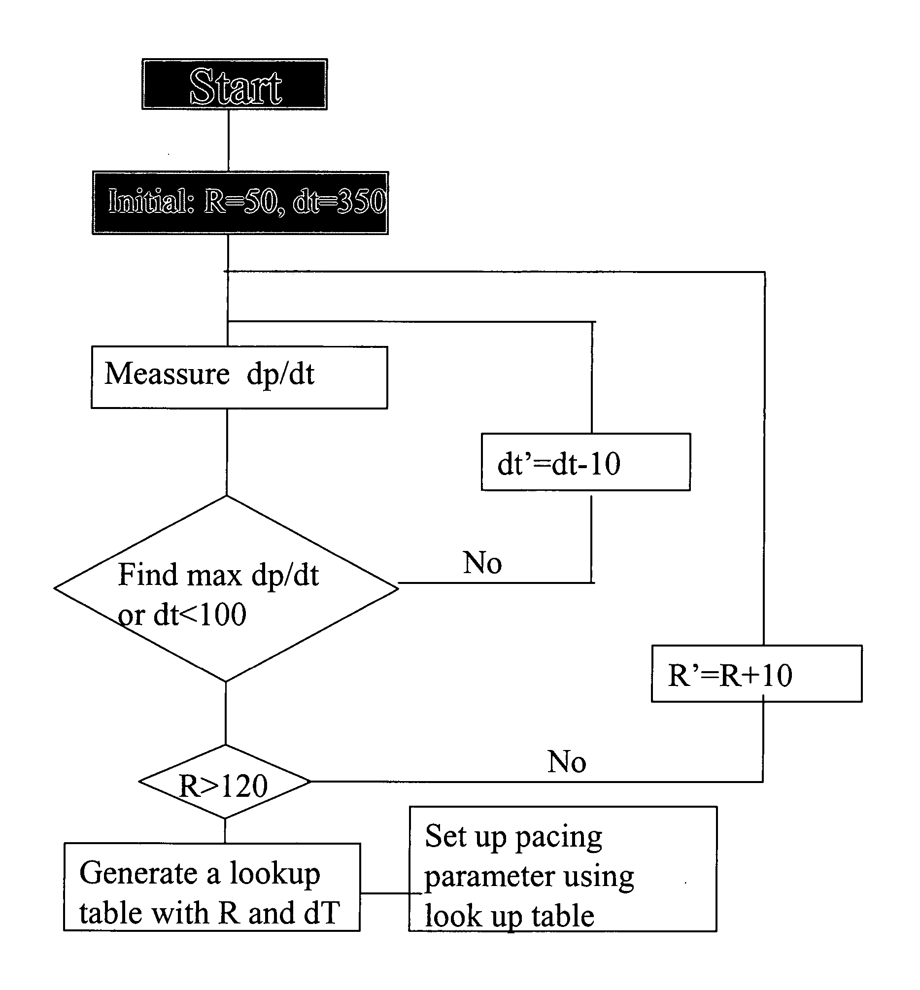
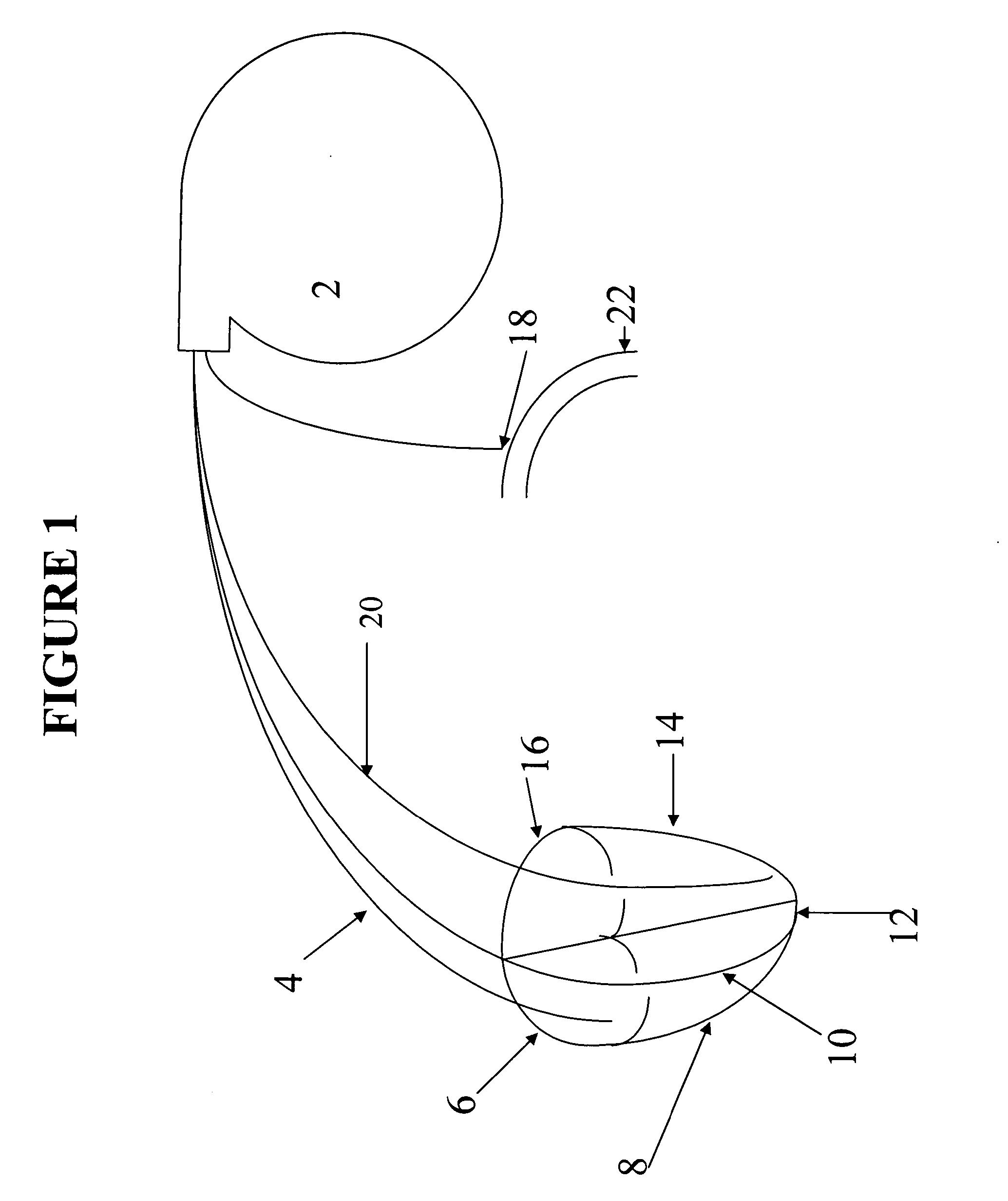
[0004] The current invention consists of pacemaker and a pacemaker catheter, or catheters. The pacemaker catheter contains pacing leads and a sensor in its' distal end of pacing catheter for sensing intracardiac pressure or a separate catheter for sensing arterial blood pressure. Intracardiac pressure measured in a real time manner by the sensor is fed back to pacemaker and used to help position the pacing leads in the cardiac chamber or chambers and to optimize the pacing setting, which result in optimization of resynchronization of myocardium and interaction among different cardiac chambers. Adjustment of pacing setting of the pacemaker can be achieved manually by a care provider or automatically by the pacemaker containing a program for this purpose. The pacemaker can sense the intracardiac pressure in a real time manner and adjust pacing setting to optimize cardiac performance. This can be done at different heart rate. It can also be performed automatically at certain time interval specified by care provider. This will further optimize resynchronization of myocardium and interaction among different cardiac chambers and, therefore, improve the function of the heart. This adjustment can be achieved manually by care provider using an interrogator. The pacemaker has capability to store information about pacing, intracardiac pressure and any adjustment the data can be retrieved for further analysis.
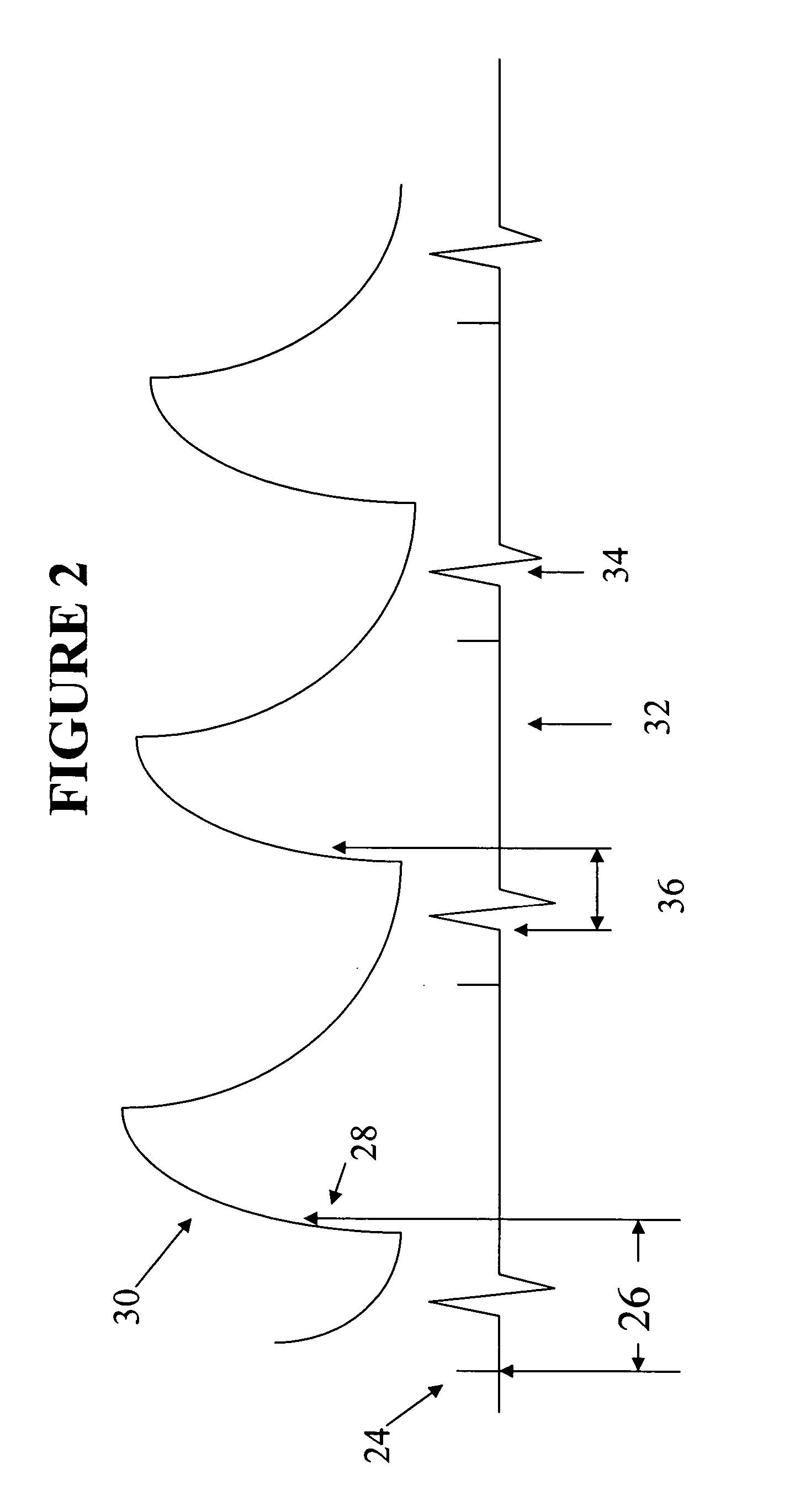
[0005] A pacing lead inserted into left ventricle raises a concern that it may cause thrombosis or infection. Alternatively, a sensor may used to sense systemic blood pressure or rate of expansion of the artery. Time difference between QRS complex from intracardiac electrocardiogram or ventricular pacing signal and maximal dp / dt of arterial blood pressure or maximal rate of expansion the artery during cardiac cycle may be used as a segregate dp / dt intracardiac pressure since shorter the time difference between QRS complex or ventricular pacing signal and dp / dt or faster the rate of expansion of the artery, the faster increase in intraventricular pressure when heart rate and contractility of the ventricle remain unchanged, meaning the ventricle needs less time to built up pressure to open the aortic valve against diastolic arterial blood pressure. Since the heart is paced at programmed rate and other factors such as arterial blood pressure, peripheral resistance and circulation volume will remain unchanged. The time difference between maximal dp / dt of arterial pressure or the fastest expansion rate of the artery and QRS complex or ventricular pacing signal will depends on dp / dt of intraventricular pressure during early diastole. The higher the maximal intraventicular dp / dt, the better the performance of the ventricle. When the ventricle is paced, A-V delay and right / left ventricular synchronization can be optimized based on time difference between intracardiac electrocardiogram or ventricular pacing signal and maximal dp / dt of the arterial blood pressure, or simply based on maximal dp / dt of the arterial blood pressure or combination of both. A sensor can be used to sense arterial blood pressure at the subclavian or axillary artery, which can be approached during insertion of the pacemaker with slight modification of the procedure of the insertion of the pacemaker. Pacing location, A-V delay, and synchronization between left and right ventricles will be adjusted based on optimal timing difference between the QRS complex of intracardiac electrocardiogram and / or maximal dp / dt of systemic blood pressure by the sensor(s) placed on the subclavical artery or other arteries. The pacemaker can sense the arterial blood pressure in a real time manner and adjust pacing setting to optimize cardiac performance. This can be done at different heart rate different workload of the heart. It can also be performed automatically at certain time interval specified by care provider. This will further optimize resynchronization of myocardium and interaction among different cardiac chambers and, therefore, improve the function of the heart. This adjustment can be achieved manually by care provider using an interrogator. The pacemaker has capability to store information about pacing, arterial pressure, intracardiac electrocardiogram and any adjustment. The data can be retrieved for further analysis. To achieve this goal, a separate sensing catheter will connect a sensor from the artery(s) to the pacemaker. If biventricular pacing is used, sensing capability for intracardiac electrocardiogram and pressure of the left ventricular lead may be eliminated. It will decrease size of the catheter, which may make it safer and easier, especially when being introduced into cardiac venous system.

Problems solved by technology

A pacing lead inserted into left ventricle raises a concern that it may cause thrombosis or infection.

Method used


Image

  • Intracardiac pressure guided pacemaker
  • Intracardiac pressure guided pacemaker
  • Intracardiac pressure guided pacemaker

Examples


Embodiment Construction

[0022] When a patient needs cardiac pacing, pacemaker leads will be in inserted into a cardiac chamber, such as the left ventricle, the pacing lead will be positioned to different location to find out which pacing location produce optimal intraventricular pressure and rate of change in the intracardiac pressure, which is likely to be maximal pressure and highest dp / dt. This is myocardial synchronization. After location of the pacing lead is determined and if contraction of the paced chamber will have to coordinate with other cardiac chamber or chambers, timing of delivery of pacing signal will be optimized based on intracardiac pressure measurement in coordination with other cardiac chamber or chambers. When more than one chamber are paced, adjustments of pacing setting for different chambers will be based on optimal pressure in a chamber interested, which is usually the left ventricle.

[0023] The optimal setting may be different at different heart rate, which can be adjusted based o...


PUM


Abstract

The current invention is an intracardiac pressure guided pacemaker. It has a sensor in pacemaker lead to sense intracardiac pressure, which is used to find the best pacing location in the cardiac chamber and to adjust the timing of pacing signal. It will optimize pacing location and pacing timing and, therefore, optimize resychronization of the contraction of myocardium and interaction between different cardiac chambers. This will improve cardiac function at the same working condition without increase in oxygen demand from myocardium. The pacemaker has a computer program, which, based on intracardiac pressure, can adjust pacing parameters of the pacemaker to optimize resynchronization of the myocardium and interaction between different cardiac chambers automatically at different heart rate and in certain time interval specified by care provider. This also can be achieved by using an interrogator manually. The pacemaker can also store profiles of pacing parameter and intracardiac pressure, which can be retrieved for review to help optimize cardiac performance.

Description

[0001] This application claims benefit of U.S. Serial No. 60 / 450,752, filed Feb. 28, 2003 and U.S. Serial No. 60 / 468,477, filed May 7, 2004, which are incorporated into this application by reference.[0002] It is known that dysynchronization of contraction of the myocardium or between different cardiac chambers causes the heart to work inefficiently. This may cause decrease in cardiac output and congestive heart failure. One way to treat this condition is ventricular or biventricular pacing, which will resynchronize contraction of ventricular muscle and activity of the atria and ventricles by using electrical stimuli from pulse generator to pace the chamber or chambers of the heart. Usually this will be achieved by adjusting the timing of pacing signals to the atria and ventricle or position pacer leads in the cardiac chambers. Some methods have been developed to adjust the timing of pacing signals. Since the purpose of biventricular pacing is to resynchronize the activities of cardi...

Claims


Application Information

Patent Timeline
IPC IPC(8): A61N1/362A61N1/365A61N1/368
CPCA61N1/3627A61N1/3684A61N1/3682A61N1/36564A61N1/36842A61N1/36843
Inventor WANG, DAI-YUAN
Owner WANG DAI YUAN
Learn More