Apparatus for releasably interconnecting structural components having a rotational symmetry

a technology of releasably interconnecting structural components and rotating symmetry, which is applied in the direction of rod connection, vehicle/pulley rope, building scaffolds, etc., can solve the problems of substantial dynamic load introduction into structural components and load imposed, and achieve the effect of optimizing the release function, reducing the triggering of undesirable loads, and preventing or greatly reducing the triggering of harmful vibrations

Inactive Publication Date: 2004-08-12
EADS SPACE TRANSPORTATION
View PDF4 Cites 6 Cited by
  • Summary
  • Abstract
  • Description
  • Claims
  • Application Information

AI Technical Summary

Benefits of technology

0016] The apparatus according to the invention permits an adaptation of the opening time duration and of the force time gradient in an optimal manner to thereby optimally reduce the triggering of undesirable loads by the release of the clamping mechanism. A controlled, gradual release of the tension force stored in the clamping mechanism prevents or greatly reduces the triggering of harmful vibrations. This important advantage is achieved according to the invention by retarding spring elements which slow down the opening motion and which shift the force time gradient of the tensioning force release toward the end of the slowed down opening motion. The retarding elements are preferably leaf springs or spiral springs or helical springs which are positioned to influence the opening motion of the tensioning levers by imposing a counter moment against the opening moment of the respective tensioning lever. By properly selecting the structural and functional characteristics of the retarding elements, particularly the springs in the form of leaf springs or helical or spiral springs, it is possible to control the release function and thereby optimize the release function by preventing uncontrolled motions of the clamping mechanism. For example, by selecting the proper dimensions and / or the material of the retarding springs the desired spring characteristics are obtained. The effectiveness of the retarding elements can be further selected by the proper positioning of the retarding elements, whereby the starting angle of the, counter-moment imposed by the retarding elements can be selected. More specifically, the time of the first contact between the tensioning lever on its way into the fully opened position and the respective retarding element can be selected by the positioning of the retarding element. The position of the retarding elements relative to the tensioning lever to be retarded advantageously influences the effectiveness of the retarding element on the respective opening motion. It has been found that particularly the triggering of low frequency vibrations can be further reduced significantly in this manner. Further, a delayed contact between the retarding element and the tensioning lever on its way into the released position does not necessarily increase the duration of the opening or tension release motion, but rather reduces the force time gradient at the end of the tension release function. Preferably the contact between the retarding element and the respective tensioning lever takes place with a contact pin that is secured to the tensioning lever and extends from the respective tensioning lever in such a direction and position that the contact pin must encounter the retarding element or elements when the tensioning lever has been released and moves toward the fully open position. This reduction in the force time gradient toward the end of the release function achieves a further substantial reduction in the triggering of vibrations and the thereby caused undesirable dynamic responses of the neighboring structural components that have been released by the opening of the clamping mechanism.

Problems solved by technology

As a result, very substantial dynamic loads may be introduced into the structural components.
Further, these loads may be imposed on areas of the structural components above and below the separation systems.

Method used


Image

  • Apparatus for releasably interconnecting structural components having a rotational symmetry
  • Apparatus for releasably interconnecting structural components having a rotational symmetry
  • Apparatus for releasably interconnecting structural components having a rotational symmetry

Examples


Embodiment Construction

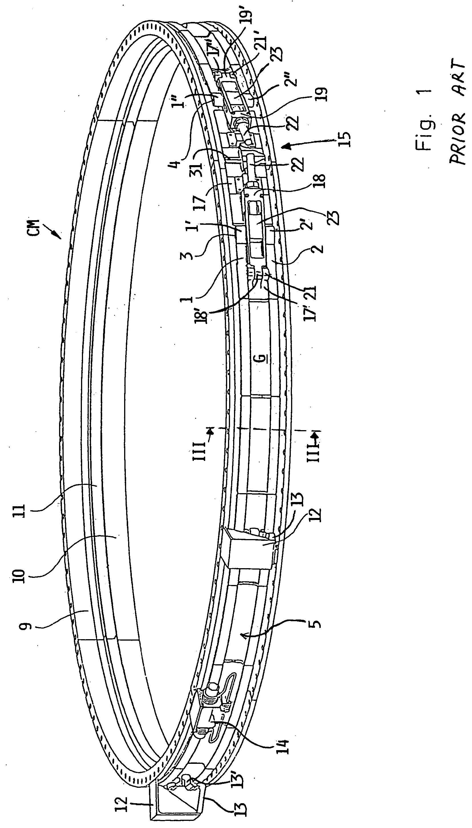
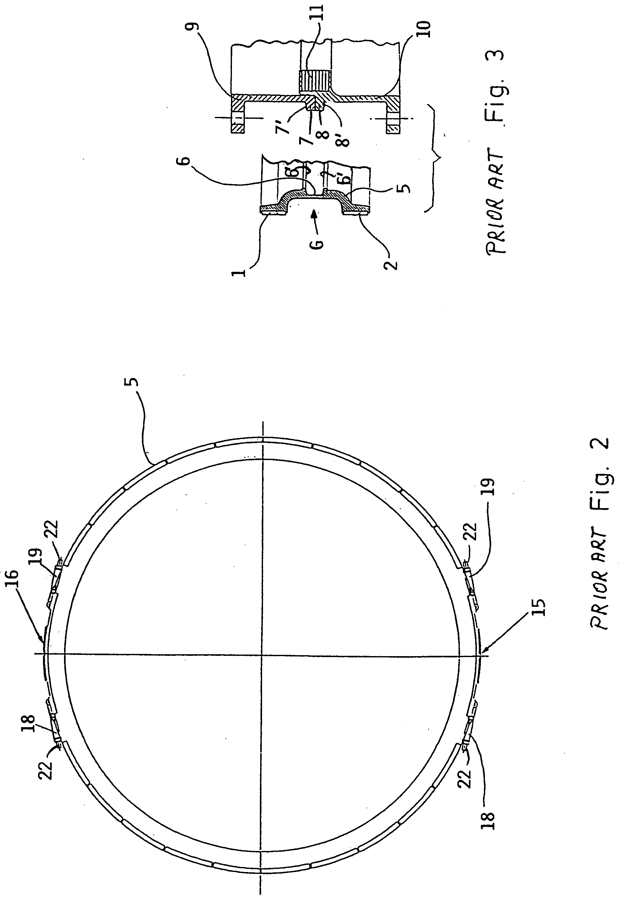
[0027] In order to provide a background context for the understanding of the invention, FIGS. 1, 2 and 3 of U.S. Pat. No. 6,588,968 B2 are now described first.

[0028] The perspective view of FIGS. 1, 2 and 3 shows a conventional clamping mechanism CM as disclosed in U.S. Pat. No. 6,588,968 B2 which describes a permanently closed ring that is formed of a plurality of clamping elements 5 circumferentially distributed around the ring shown in a tensioned and locked condition. The diameter of the permanently closed ring can be reduced for locking and increased for unlocking. The clamping elements 5 are held together by two tensioning members 1, 2 such as straps, tapes, belts or cables which are spaced from each other in the vertical or axial direction. The axial direction is defined as the central longitudinal axis of the structural components (not shown) to be releasably clamped together. The strap 1 has an eye 1' at one end and an eye 1" at the other strap end. The strap 2 has an eye 2...


PUM


Abstract

Two structural components having a rotational symmetry relative to a central longitudinal axis, are releasably connected to each other by a clamping mechanism which engages two interface rings secured to the respective structural component. The clamping mechanism is formed by tensioning elements (5) held together by at least one, preferably two straps (1, 2). A lock (15) with two hinged tensioning levers holds the strap or straps releasably together. For this purpose each strap end is journalled by a journal bolt to the tensioning lever (18, 19). Locking elements (25, 26, 28, 30) hold the tensioning lever (18, 19) in a locked position in the lock. An electromagnetic drive or the like unlocks the tension levers for releasing the tensioning strap or straps, whereby the opening motion of the tensioning levers is retarded or delayed by one or more springs in a controlled manner to avoid or at least optimally reduce the triggering of harmful vibrations and the introduction of undesirable loads in the components being released.

Description

CROSS-REFERENCE TO RELATED U.S. PATENT[0001] This application is related to U.S. Pat. No. 6,588,968 B2, issued on Jul. 8, 2003, based on U.S. Ser. No. 09 / 801,174, filed Mar. 5, 2001. The entire disclosure of said U.S. Patent is incorporated herein by reference.PRIORITY CLAIM[0002] This application is based on and claims the priority under 35 U.S.C. .sctn.119 of German Patent Application 103 01 783.6, filed on Jan. 18, 2003, the entire disclosure of which is incorporated herein by reference.[0003] The invention relates to a clamping mechanism for releasably interconnecting structural components of rotational symmetry such as cylindrical or conical bodies. An example is the connection of a payload to a carrier rocket. The clamping mechanism forms a tensioning ring which is capable of releasing one structural component from the other structural component without completely opening the ring.BACKGROUND INFORMATION[0004] Such a clamping mechanism encircles the structural components to be ...

Claims


Application Information

Patent Timeline
Patent Type & Authority Applications(United States)
IPC IPC(8): F16B2/08B64G1/64F16B1/00F16L21/06F16L23/04
CPCB64G1/641B64G1/645F16L21/06Y10S403/07Y10S403/09Y10T403/7062Y10S403/14Y10T403/7182Y10T403/54Y10T403/535Y10T403/453Y10S403/04
Inventor HUESSLER, WALTER
Owner EADS SPACE TRANSPORTATION
Why Eureka
Try Eureka