Motor-driven cutting device

a cutting device and motor technology, applied in the field of motor-driven cutting devices, can solve the problems of affecting the cutting effect, and the risk of inflicting injuries on patients, so as to improve the cutting effect, simplify the guidance of the device, and work with a particular efficiency

Inactive Publication Date: 2004-06-24
KRATZMAIER KONSTRUKTIONEN
View PDF10 Cites 11 Cited by
  • Summary
  • Abstract
  • Description
  • Claims
  • Application Information

AI Technical Summary

Benefits of technology

0017] The cutting tools themselves preferably are mainly plain and are sliding along each other with their surfaces during their relative movement. They may provide a convex cutting edge, which either allows for a shearing effect or a knife-like effect on the material to be cut. The cutting edge in particular may also be provided with teeth in order to engage with the object to be cut especially effective. These teeth in particular may also be present at just one cutting edge, e.g. at the cutting edge of the movable cutting tool.
0018] According to a further advantageous embodiment of the invention, a significant friction is allowed to occur between a cutting edge of a movable cutting tool and the flat object to be cut, especially in consequence of the mentioned teeth, so that the device with its cutting tools--in consequence of the movement components comprising one component in the flat object's plane--travels through the object along a cutting line. The cutting tool movement according to the invention can thus --besides improved cutting results--also offer a simplification of guidance of the device by an operating person, wherein this person is no more obliged to use physical effort to produce a sufficient pressure in order to properly convey the cutting tool along the bandage or the suit or another object.
0019] In a preferred embodiment, the cutting tool unit according to the invention is equipped both with two movable cutting tools and a further, static cutting tool, which is located between these movable cutting tools. Thus, a cutting process is realised on both sides of the static cutting tool, allowing the machine to work with a particular efficiency. In case of using dephased movement of the two movable cutting tools, a mass balance can be achieved, if desired. Moreover, by using the two movable cutting tools flanking the static cutting tool having a certain width, it is possible, not just to generate a linear cut in the flat object, but to cut out a strip from the flat object. This can facilitate the subsequent opening of a stiff bandage or a protective suit.
0020] The driving motor unit preferably allows for a continuous regulation of the motor speed and thus of the cutting tool movements. In particular, the driving motor unit can provide a button for switching on and, resulting from a release of the button, for switching off said driving motor unit, wherein the intensity of pressure exerted on the button, or the depth, by which the button is pushed into a guideway, can serve to adjust the driving speed.

Problems solved by technology

In particular when cutting open bandages and especially stiff bandages, one encounters major problems when using purely hand-operated scissors and other tools.
Common bandages are already rather difficult to be cut open by means of scissors and furthermore bear a certain risk of inflicting injuries to the patient in consequence of the applied physical forces.
These problems especially and in a pronounced manner apply to the opening of stiff bandages made of plaster or plastics.
Similar problems however e.g. also arise when opening the protective suit of a motorcyclist during first aid at the accident place.

Method used


Image

  • Motor-driven cutting device
  • Motor-driven cutting device
  • Motor-driven cutting device

Examples


Embodiment Construction

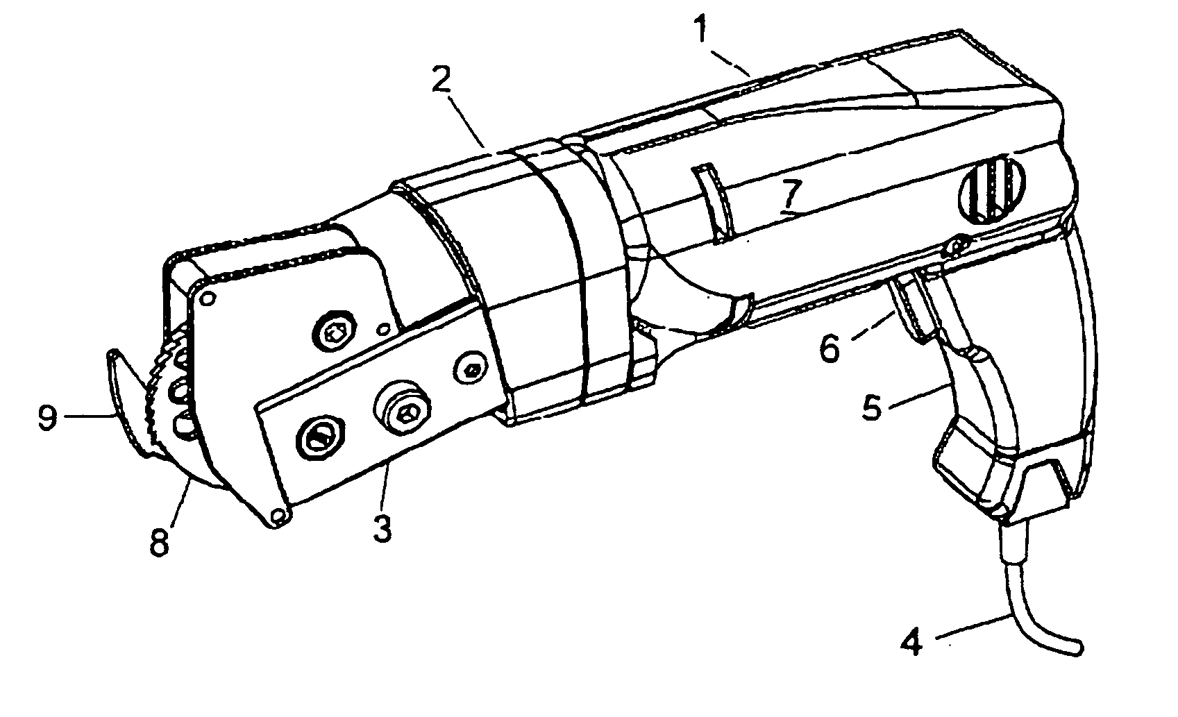
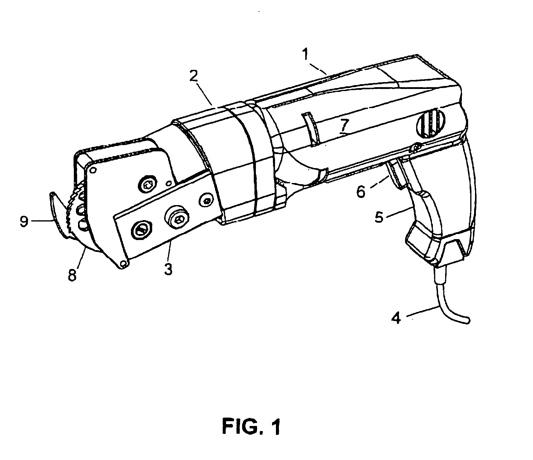
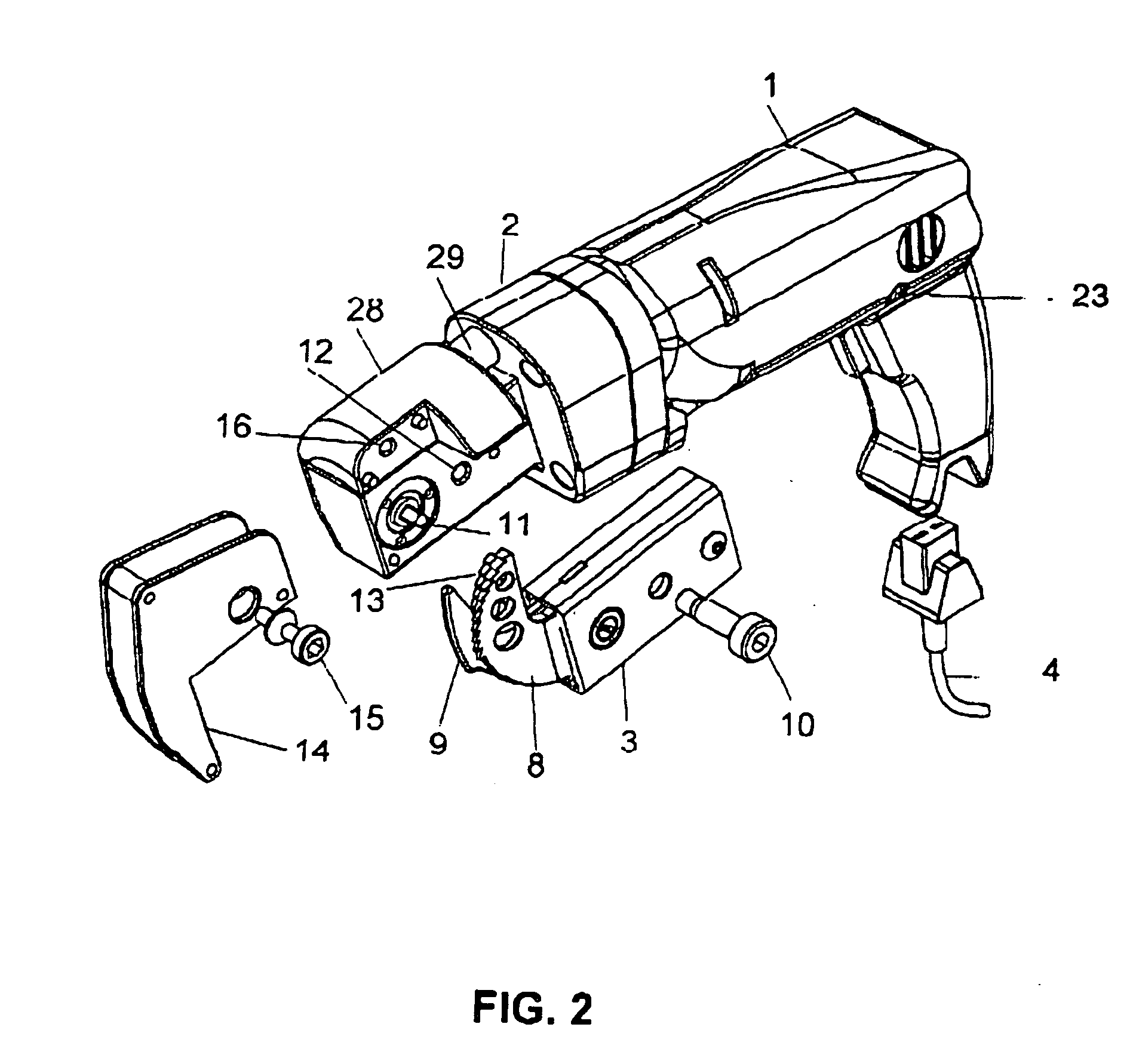
[0028] In FIG. 1 one envisages a cutting device according to the invention, comprising a driving motor unit 1, a gear unit 2 and a cutting tool unit 3. Driving motor unit 1 here is a conventional electrical drilling machine with a power cable 4, an operating handle 5, a button 6 for switching on and controlling speed and, finally, with an electrical motor not being visible in FIG. 1, but being located in a housing part indicated by numeral 7. A gear unit 2 is attached at the side of driving motor unit 1 being depicted in the left front part in FIG. 1, wherein this gear unit in particular contains a gear reduction for increasing the torque and reducing the rotational speed and for reversing the rotational direction by 90.degree.. A driven shaft of driving motor unit 1 (see 11 in FIG. 2)--as it is typical for such drilling machines--is positioned along the longitudinal axis of the total device shown in FIG. 1. The rotation axis of the driven shaft (not depicted in FIG. 1) of gear unit...


PUM

PropertyMeasurementUnit
temperatureaaaaaaaaaa
frictionaaaaaaaaaa
velocityaaaaaaaaaa

Abstract

The invention refers to a novel device for cutting flat objects, in particular for cutting stiff bandages and protective suits. The device provides at least one movable cutting tool (8, 13), which is able to perform a movement, that can be assigned to a closed line surrounding a finite area.

Description

[0001] This invention refers to a motor-driven cutting device for cutting flat objects. The device is intended to be employed as a hand-held apparatus, i.e. it should be possible to hold it--as a complete apparatus--with one or both hands. The invention is preferably directed to devices, which are designed for cutting open flat objects surrounding the human body, in particular stiff bandages, protective clothing like motorcyclist suits etc. It is however also directed to hand-held cutting devices for cutting open flat objects of other kind.PRIOR ART[0002] In particular when cutting open bandages and especially stiff bandages, one encounters major problems when using purely hand-operated scissors and other tools. Common bandages are already rather difficult to be cut open by means of scissors and furthermore bear a certain risk of inflicting injuries to the patient in consequence of the applied physical forces. These problems especially and in a pronounced manner apply to the opening...

Claims


Application Information

Patent Timeline
Patent Type & Authority Applications(United States)
IPC IPC(8): A61F15/02B23D29/00B26B7/00B26B15/00
CPCA61F15/02B26B15/00B26B7/00B23D29/005Y10T83/04
Inventor KRATZMAIER, ERICH
Owner KRATZMAIER KONSTRUKTIONEN
Why Eureka
Try Eureka