
Illuminated background display apparatus

a display apparatus and background technology, applied in the field of illumination display apparatus, can solve problems such as the risk of reducing the visibility of the obj

Inactive Publication Date: 2004-05-20
SOTEK
View PDF15 Cites 38 Cited by
  • Summary
  • Abstract
  • Description
  • Claims
  • Application Information

AI Technical Summary

Benefits of technology

0031] The light source may be partially covered by a reflective material in order to prevent viewing of a body of the light source from a point external to the display.

Problems solved by technology

However, such prior art illumination arrangements suffer from the disadvantage that grooves are positioned in the line of sight of the viewer, thus further diffusive stage such as Fresnel lens must be added to the assembly, as for example in European Patent Publication No. 879991.
A serious problem with this approach however is that visibility may be critically reduced when the screen is viewed from an off-perpendicular position.

Method used


Image

  • Illuminated background display apparatus
  • Illuminated background display apparatus
  • Illuminated background display apparatus

Examples


Embodiment Construction

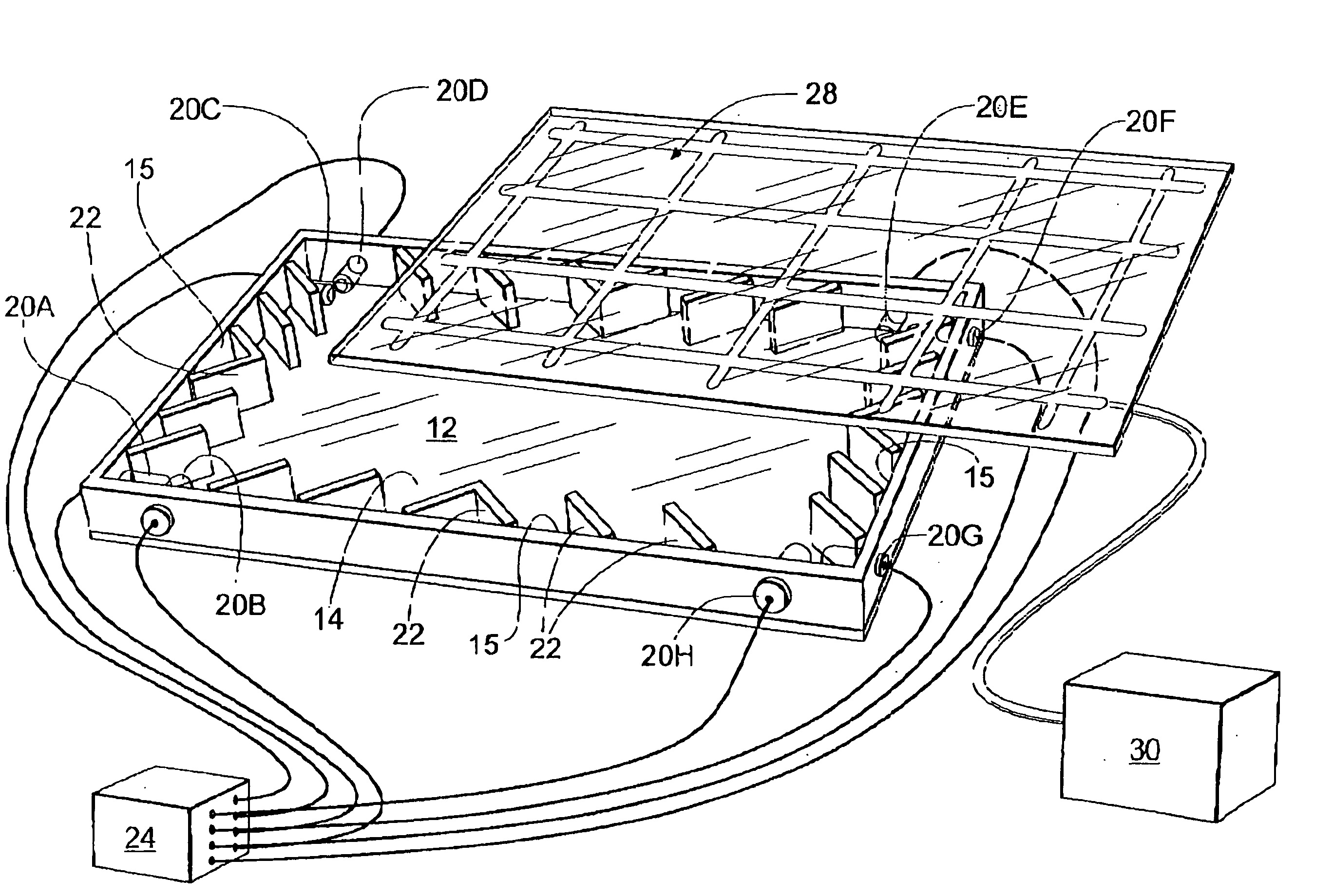
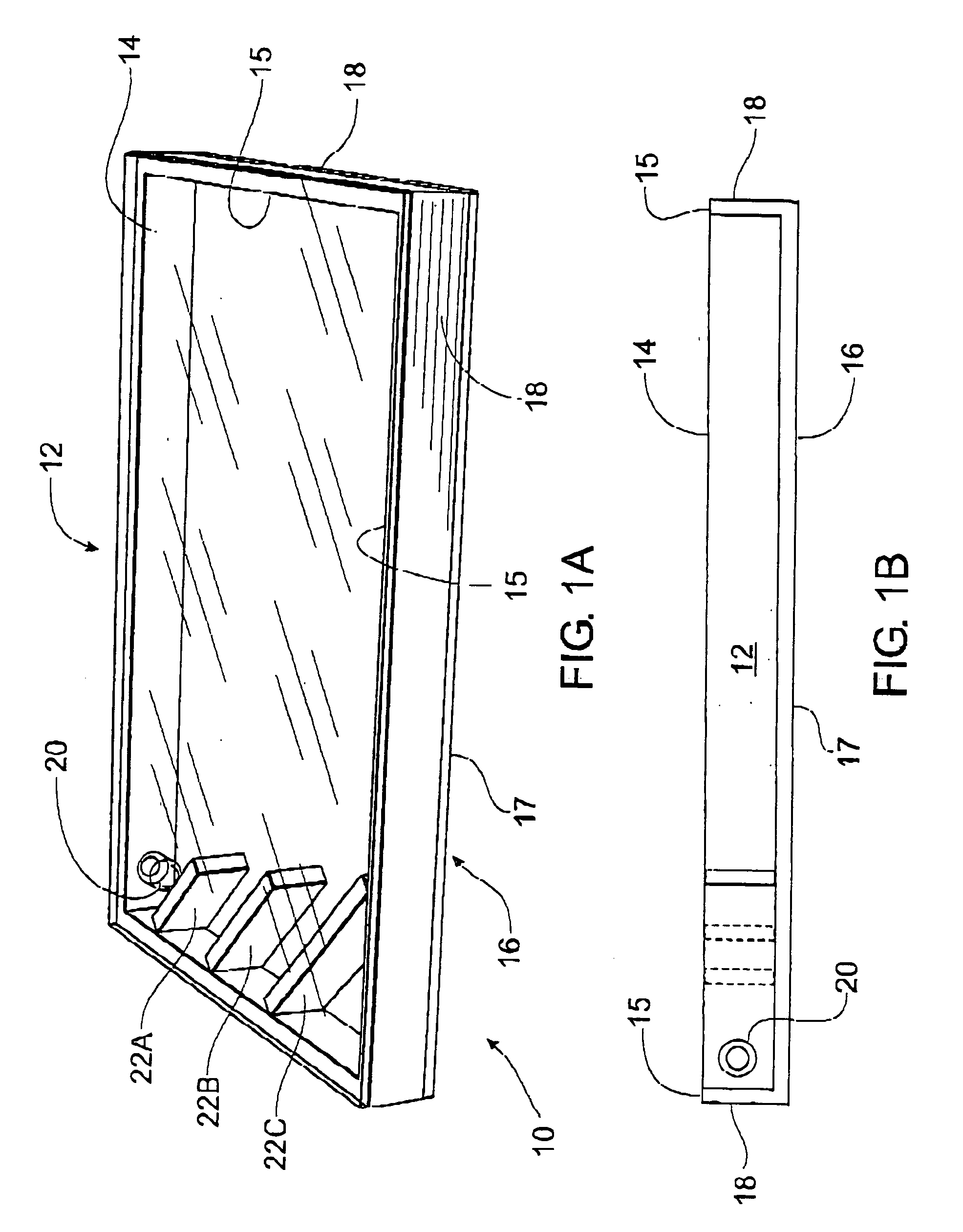
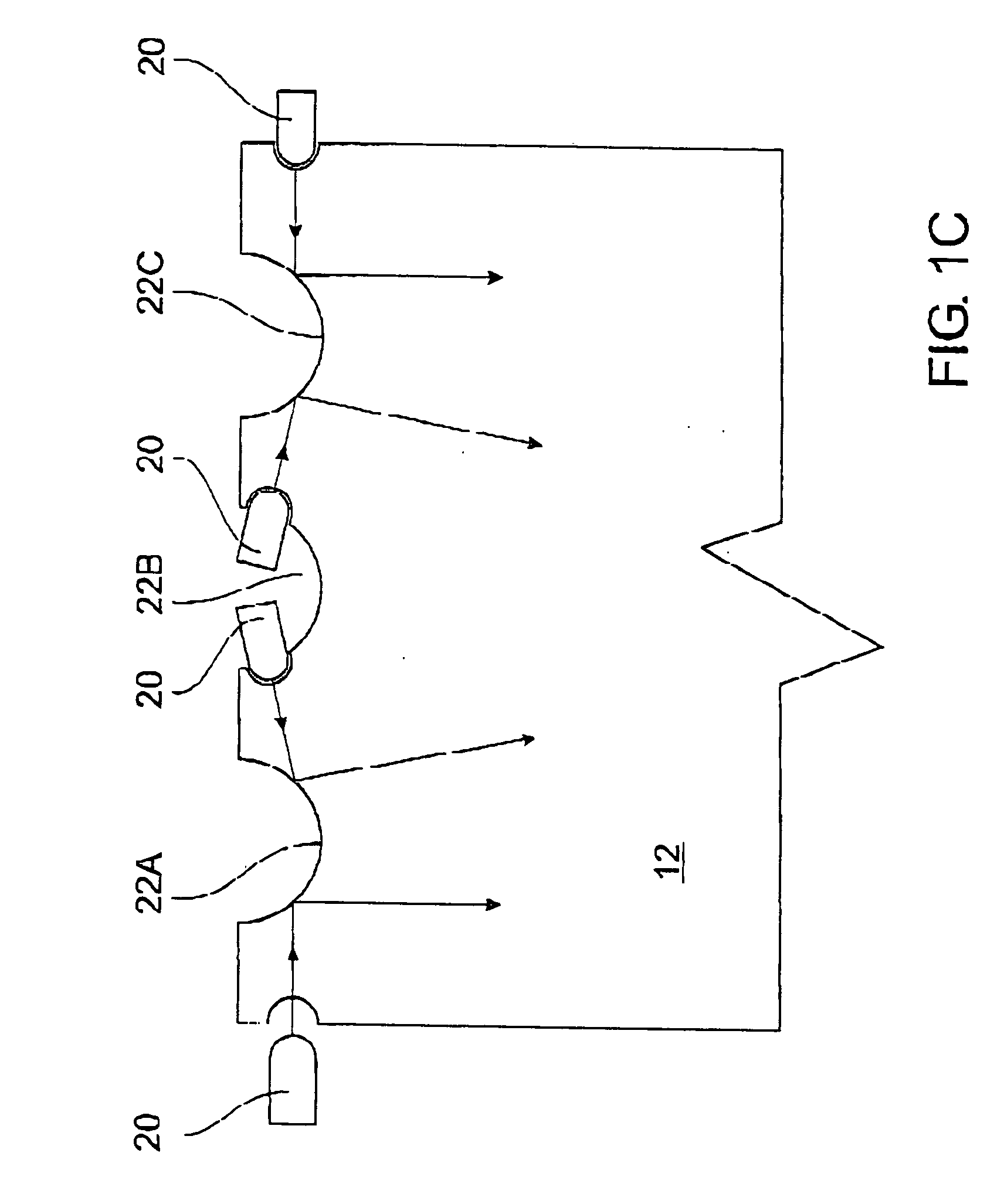
[0053] Referring now to FIGS. 1A and 1B, there is depicted a display apparatus 10 according to an embodiment of the present invention. The display apparatus includes a substrate formed by single slab or sheet 12 of optically transparent material. Any stable, optically transparent material having a refractive index greater than air will be suitable. For example, clear acrylic, glass and polyethylene are all suitable. Although shown as having a rectangular form, the substrate could be formed in any desired shape. The sheet 12 has parallel upper 14 and lower 16 faces as shown. In the example depicted there are four edge faces 15, each of which is treated with an inwardly reflecting mirror coating 18.

[0054] For use as a back-light source the lower face 16 of sheet 12 is in contact with a white material 17 so that no air-gap is present between the material and the lower face of the sheet. The white material 17 operates to capture light from sources within sheet 12 and to reflect the ligh...


PUM

PropertyMeasurementUnit
angleaaaaaaaaaa
angleaaaaaaaaaa
angleaaaaaaaaaa

Abstract

An illuminating display including a transparent substrate (12) in the form of a sheet or slab having an upper face (14), a lower face (16) and a plurality of edge faces. The edge faces are provided with an internally reflective treatment (18) and at least one light source (20) is associated with the substrate, causing a relatively narrow beam of light rays to emanate into said substrate. At least one reflective surface (22) arranged internally, preferably perpendicular to either the upper or lower face, of said substrate (12) to operatively internally reflect light rays (26) from said light source (20) within the substrate. Either (or both) the upper face (14) and the lower face (16) having material (17) in contact therewith for capturing or directing light from within the substrate out of a face (14, 16). The display may be employed in combination with a liquid crystal display (LCD) assembly.

Description

[0001] 1. Field of the Invention[0002] The present invention is concerned with an illuminated display apparatus. The invention finds particular, although not exclusive, application as a means for back-lighting liquid crystal displays (LCDs).[0003] 2. Discussion of the Background Art[0004] Back-illuminated flat panels have typically incorporated either an edge located light batten or a straight fluorescent tube positioned along the length of an edge of the panel. Prior art arrangements of the above type that use linear light sources are disclosed in U.S. Pat. No. 5,219,217 to Aikens and European Patent Publication No. 879991 in the name of Matsushita Electric Industrial Co., Ltd. for example.[0005] Such illuminated panels are characterised by the use of reflective surfaces provided either adjacent to or within the panel, which surfaces are arranged to reflect light from the linear source out through a major surface of the panel towards an observer. Typically reflective surfaces are a...

Claims


Application Information

Patent Timeline
Patent Type & Authority Applications(United States)
IPC IPC(8): F21V8/00G02F1/13357F21Y101/02G02B6/00G09F13/02G09F13/18
CPCG02B6/0018G02B6/0096G02B6/0055G02B6/0028
Inventor BLACH, TOMASZ
Owner SOTEK
Learn More