


Quick Research
Generate reliable direction feasibility study reports for your R&D in just a few steps.

Technical Q&A
Discover and master advanced knowledge NOW. Basics, ideas, possibilities, all at once.

Find Solutions
As an expert in R&D theories, this can generate solutions to your technical problems instantly.

Evaluate Feasibility
Analyze your overall solution with one click, know your potential R&D risks in advance.

Monitor Landscape
Get weekly tech updates, stay abreast of the latest tech innovations and key insights.
Catalyst-coated ionomer membrane with protective film layer and membrane-electrode-assembly made thereof
- Summary
- Abstract
- Description
- Claims
- Application Information
AI Technical Summary
Benefits of technology
Problems solved by technology
Method used
Image

Examples
first embodiment
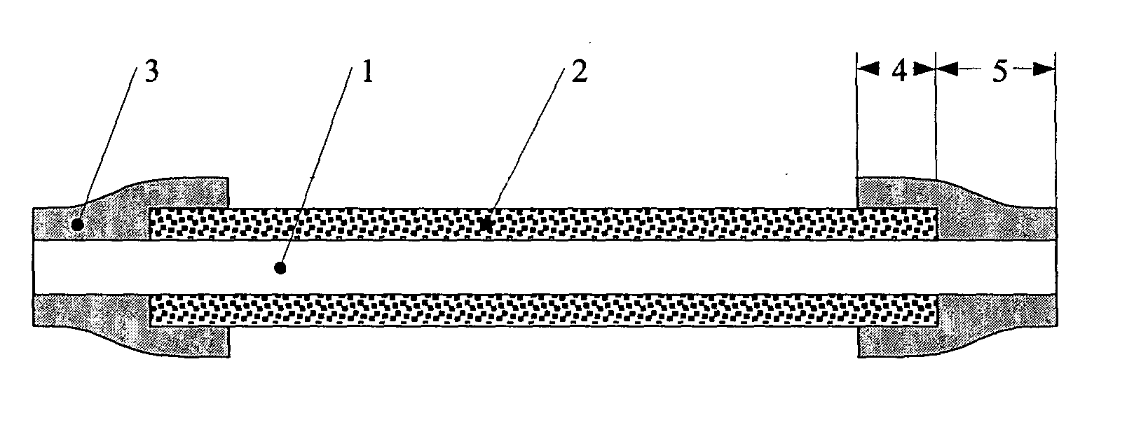
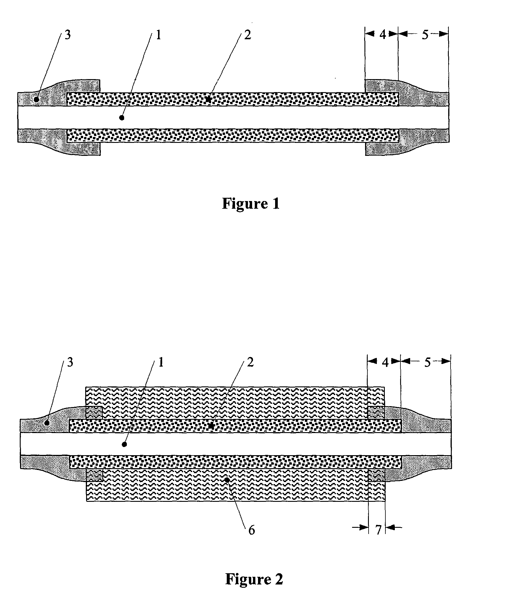
[0053] FIG. 1 shows a schematic drawing (cross section) of a catalyst-coated membrane (CCM) according to the present invention. According to this embodiment, the ionomer membrane (1) is coated on both sides with an electrode layer (2) forming the active area of the catalyst-coated membrane. Two frames of protective film layer (3) are applied on both sides to the passive area of the membrane (1) in such a way that the film layers overlap with the electrode layers in an area region (4), and, simultaneously, with the passive, non-coated area of the ionomer membrane in an area region (5). On each side of the membrane, the region covered or overlapped by the protective film layer is in the range of 0.5 to 20% of the total active area of the membrane.
[0054] The protective film may be made of a polymer that is more rigid than the ionomer membrane. The thickness of the protective film is preferably in the range of 10 microns to 150 microns (more preferably in the range of 80 to 120 microns)...
example 1
[0062] The catalyst-coated membrane used in this example was manufactured according to U.S. Pat. No. 6,309,772, example 3, ink A. A 40 wt. % Pt / Vulcan XC72 catalyst was used as cathode catalyst, and a 40 wt. % PtRu (1:1)Vulcan XC72 was employed for the anode side. The CCM product is available at OMG under the designation "CCM-Type 7C" and was used with a 100 cm.sup.2 (10.times.10 cm) of active area. The passive area (the non-coated area) of the CCM had a size of 1.0 cm in width, resulting in overall CCM dimensions of 12.times.12 cm with the active area centered in the middle.
[0063] Co-polyamide Vestamelt 3261 (Degussa, Duisseldorf) was provided as an extruded film of 120 .mu.m thickness. From this film, two square-sized frames were punched with inner dimensions of 9.8.times.9.8 cm and outer dimensions of 12.times.12 cm.
[0064] The catalyst-coated membrane was placed between the two frames of protective film, and the assembly was covered by two sheets of PTFE blanks. The protective fi...
example 2
[0067] A catalyst-coated membrane (CCM) with protective film layers on both sides was prepared according to the procedure described in example 1. Instead of the co-polyamide material, a polyurethane-based film material (Walopur 4201AU, Epurex / Germany) with a thickness of 90 .mu.m was used as the protective film layer. Lamination parameters were 27 bar and a temperature of 145.degree. C. for 2 minutes. The overlapping area of the protective film was about 5% of the total active area on both sides of the CCM. Furthermore, the overlapping area of the protective film with the non-coated area was about 100% of the total non-coated area. The catalyst-coated membrane and two GDLs were again mounted into a PEM single cell and tested in hydrogen / air operation at 1.0 bar / 70.degree. C. for an extended period of 300 hours. An excellent long-term performance was obtained. Microscopic inspection of the catalyst-coated membrane showed no indications for damage, either in the protective layers or a...
PUM
 Abstract
Description
Claims
Application Information
 - R&D Engineer
- R&D Manager
- IP Professional
- Industry Leading Data Capabilities
- Powerful AI technology
- Patent DNA Extraction
Browse by: Latest US Patents, China's latest patents, Technical Efficacy Thesaurus, Application Domain, Technology Topic, Popular Technical Reports.
© 2024 PatSnap. All rights reserved.Legal|Privacy policy|Modern Slavery Act Transparency Statement|Sitemap|About US| Contact US: help@patsnap.com