
Custom molded wrist area impression kit and method

Inactive Publication Date: 2004-04-22
STESS RICHARD M +1
View PDF1 Cites 6 Cited by
  • Summary
  • Abstract
  • Description
  • Claims
  • Application Information

AI Technical Summary

Benefits of technology

[0010] A further object of the present invention is to provide a method of forming a custom molded wrist area impression kit which is suitable for home use as well as use by medical technicians.
[0012] Still a further object of the present invention is to provide a custom molded wrist area impression cast and method which are suitable for scanning to enable the subsequent formation of an immobilizing wrist cast.

Problems solved by technology

Motocross motorcycle riders, for example, are at risk for painful wrist injuries as a result of dynamic shock loads which can over-extend the wrist, pulling or tearing ligaments and tendons.
Since these systems employ multiple layers and various combinations of hardening materials, they are tedious and difficult to form on the patient in order to achieve the highly desirable custom fit.
Such custom casting, it will be understood, is often undertaken when the patient is in pain or experiencing considerable discomfort, making the construction of a cast in situ a disagreeable experience.
As the casting time becomes longer due to the complexity of forming a cast with sufficient rigidity to support the patient, it is more difficult to maintain the desired patient orientation or positioning.
Since in situ casting is often accomplished using resins which produce considerable heat during rigidification, another problem is providing sufficient thermal insulation between the patient and the various casting layers, which can contain a substantial volume of resin.
The thermal insulation required to withstand exothermic resin curing again makes the process of in situ casting more complex and tedious, as well as interposing layers between the patient and the eventual rigid cast which can affect cast fit.
The molding system, however, is messy in its use, requiring the pouring of the hardening resin between two fabric sleeves and thereafter dispersing of the resin evenly throughout the casting fabrics before hardening using a roller.

Method used


Image

  • Custom molded wrist area impression kit and method
  • Custom molded wrist area impression kit and method
  • Custom molded wrist area impression kit and method

Examples


Embodiment Construction

[0021] The wrist area impression sleeve, kit and method of the present invention are particularly well suited for formation of a hardened, removable wrist brace that can be custom molded at home by the patient or brace user. The same kit, however, also can be used to make an immobilizing orthopedic cast by medical personnel, either directly on the patient or in the laboratory after removal of the hardened casting sleeve.

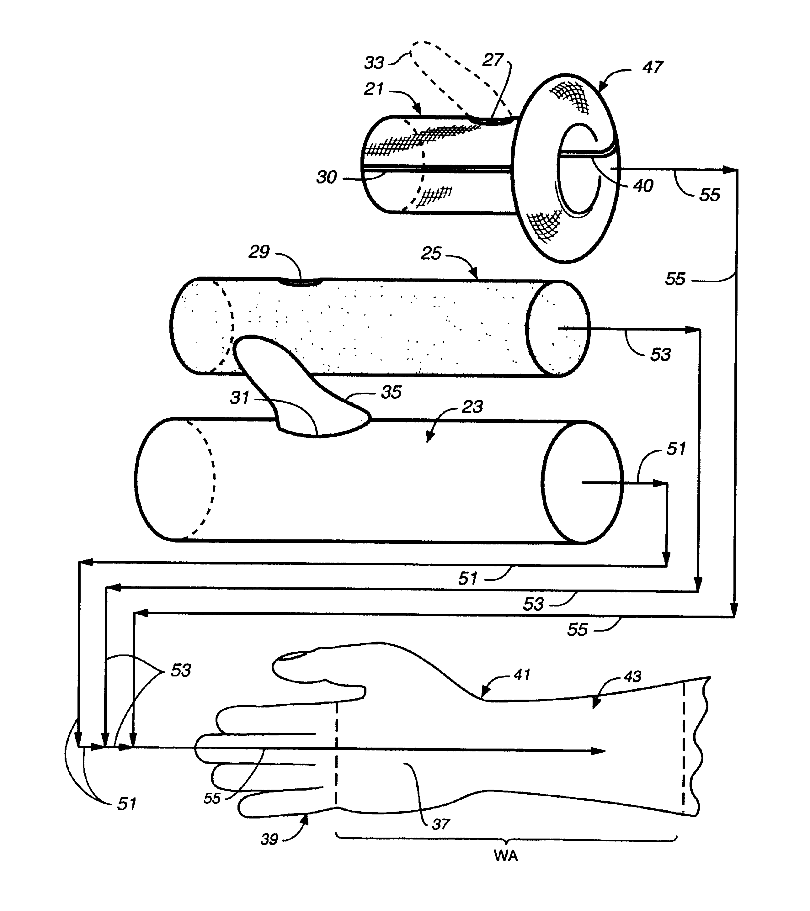
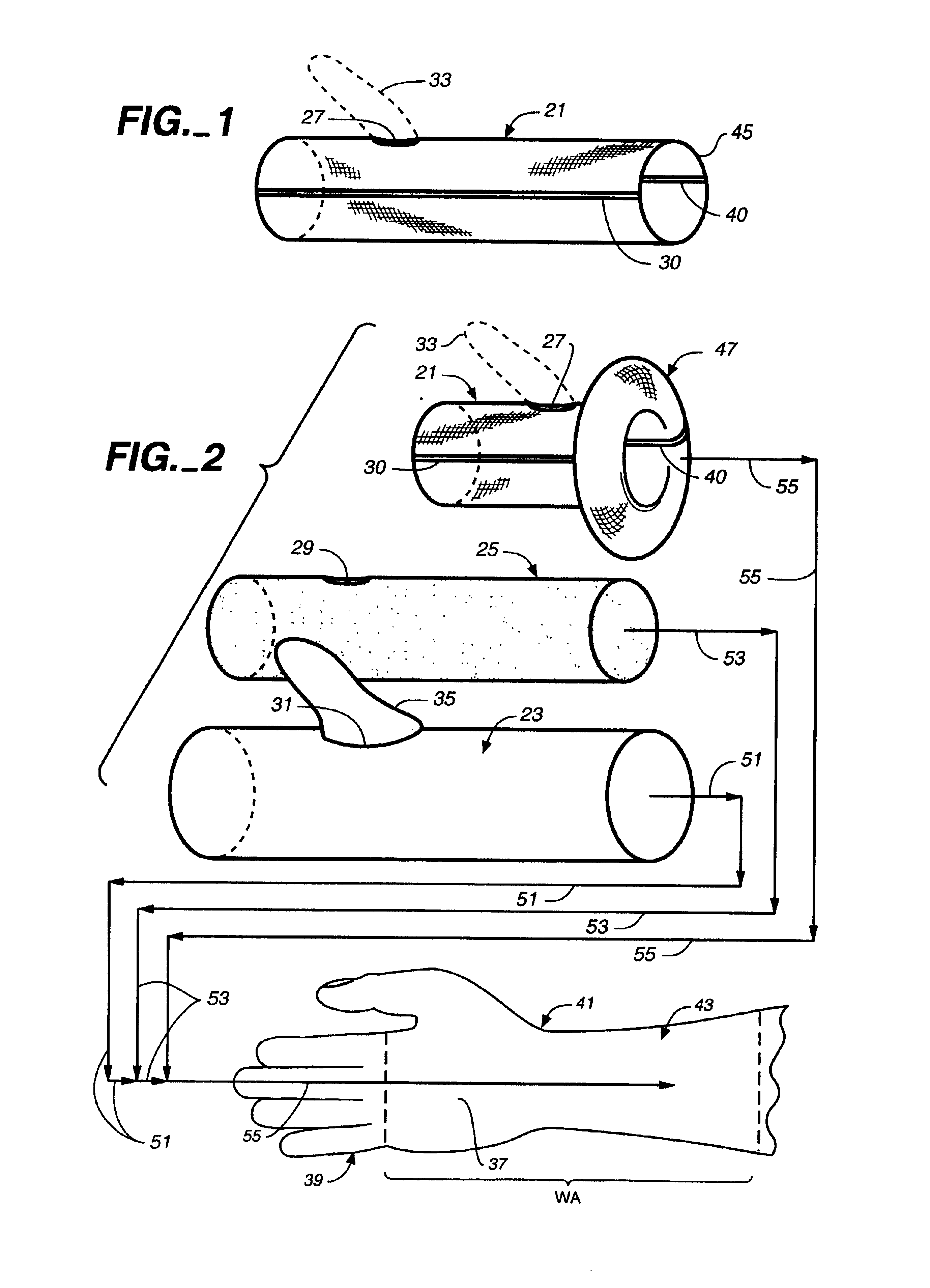
[0022] Referring now to the drawing, the present wrist area impression kit for custom molding of a wrist brace is based upon the use of a relient, elongated, tubular, hardenable impression sleeve 21. As will be seen in FIG. 2 and as is set forth hereinafter below, sleeve 21 may be used with various other components such as release member or tube 23, and / or cushioning sleeve 25.

[0023] Impression sleeve 21 of the present invention can advantageously be formed of synthetic fabric material, such as lofted glass yarn or polyester yarn, and it is preferably knit with elast...


PUM


Abstract

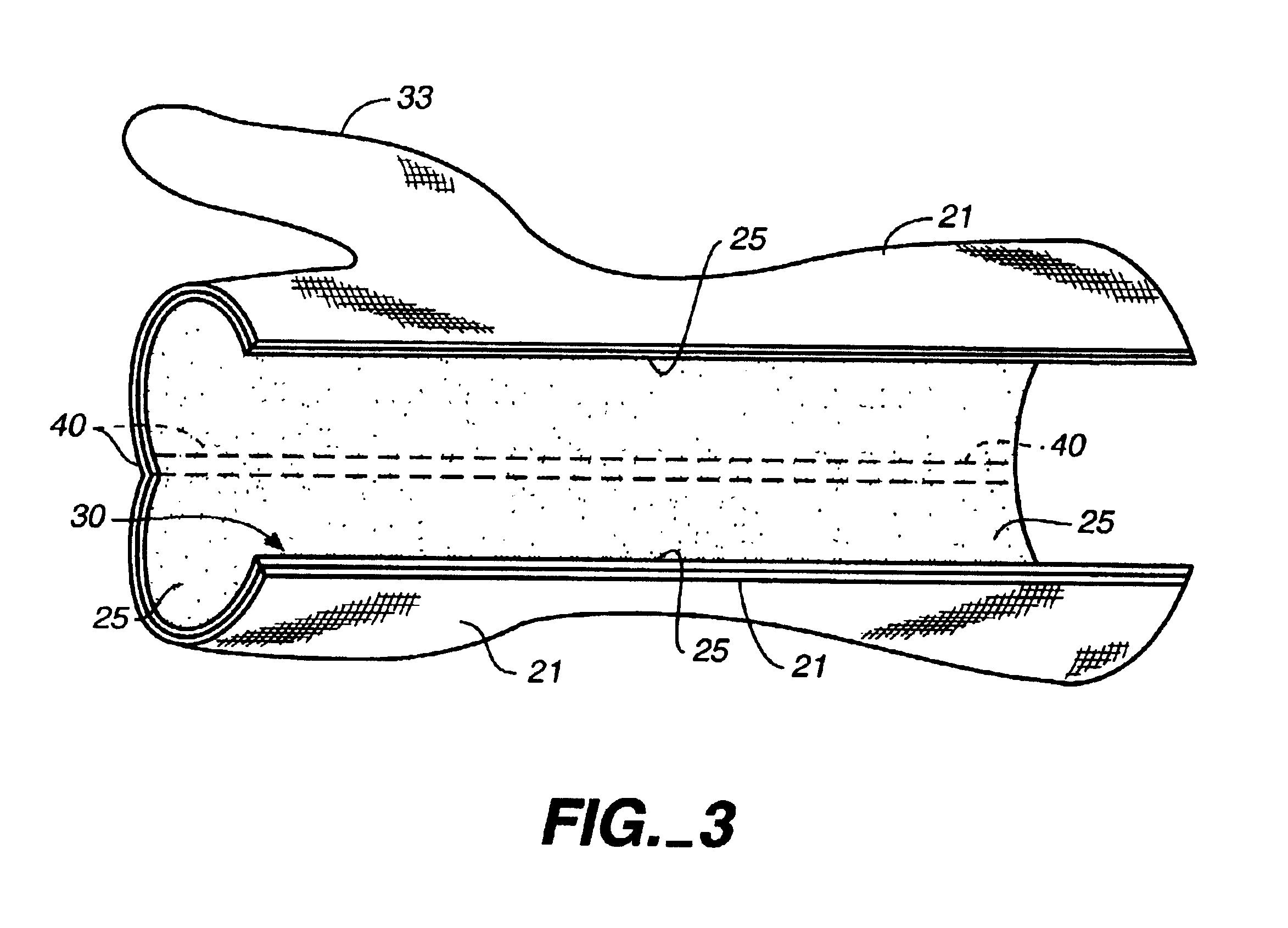
Custom molded wrist area impression sleeve (21) having a configuration substantially covering the wrist area (WA) of a patient. The impression sleeve (21) is formed from a thin, resin-impregnated, resilient fabric sleeve (21) mounted over a thin, flexible, resin-impervious release layer (23), and preferably over a cushioning and thermally insulating foam sleeve (25). The hardenable sleeve (21) can include one, and preferably two, longitudinally extending weakened strips (30, 40) which facilitate severing and act as a hinge (40) for the resulting hardened wrist brace. In the present method, the wrist area impression sleeve (21) is hardened on the patient's wrist, cut off and then used as a removable brace or to form a custom orthosis in a fabrication laboratory.

Description

[0001] This invention relates, in general to custom molded orthopedic braces, and more particularly, relates to methods and apparatus for the formation of a custom molded impression of a patient's wrist area which can be used to form an immobilization cast or wrist brace.[0002] Custom casting of a patient's wrist area can be employed to effect relatively complete immobilization of the wrist, for example, to heal a broken bone, or merely to limit wrist motion, for example, to treat carpal tunnel syndrome or to prevent over-extension of the wrist while performing various tasks. Motocross motorcycle riders, for example, are at risk for painful wrist injuries as a result of dynamic shock loads which can over-extend the wrist, pulling or tearing ligaments and tendons. A removable custom molded wrist brace which permits limited motion and yet will resist extreme wrist articulation under dynamic loading would be highly desirable for such activities.[0003] As used herein, the expression "wr...

Claims


Application Information

Patent Timeline
IPC IPC(8): A61F5/01A61F13/04
CPCA61F13/04A61F5/0118
Inventor STESS, RICHARD M.GRAF, PETER M.
Owner STESS RICHARD M
Learn More