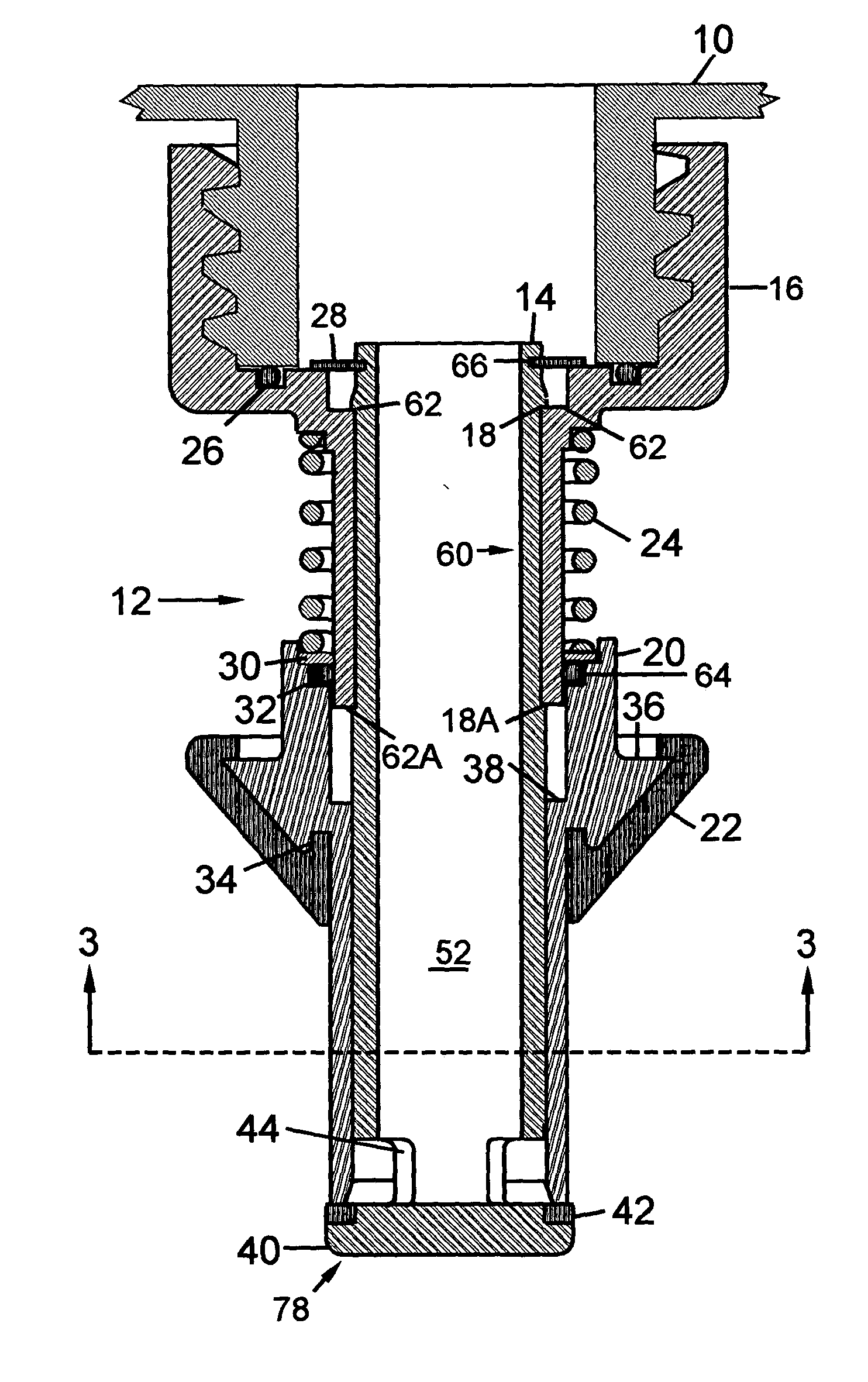
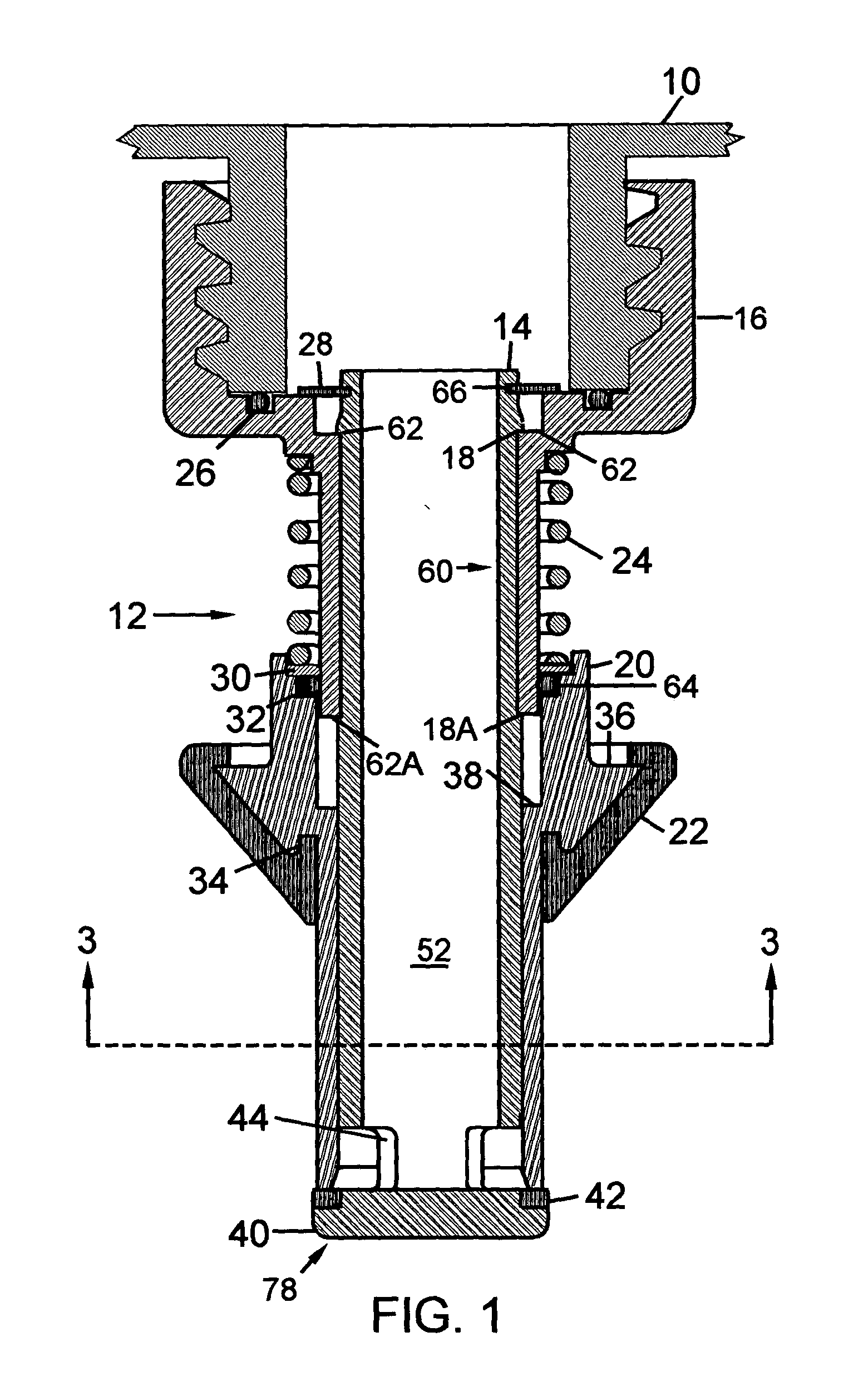
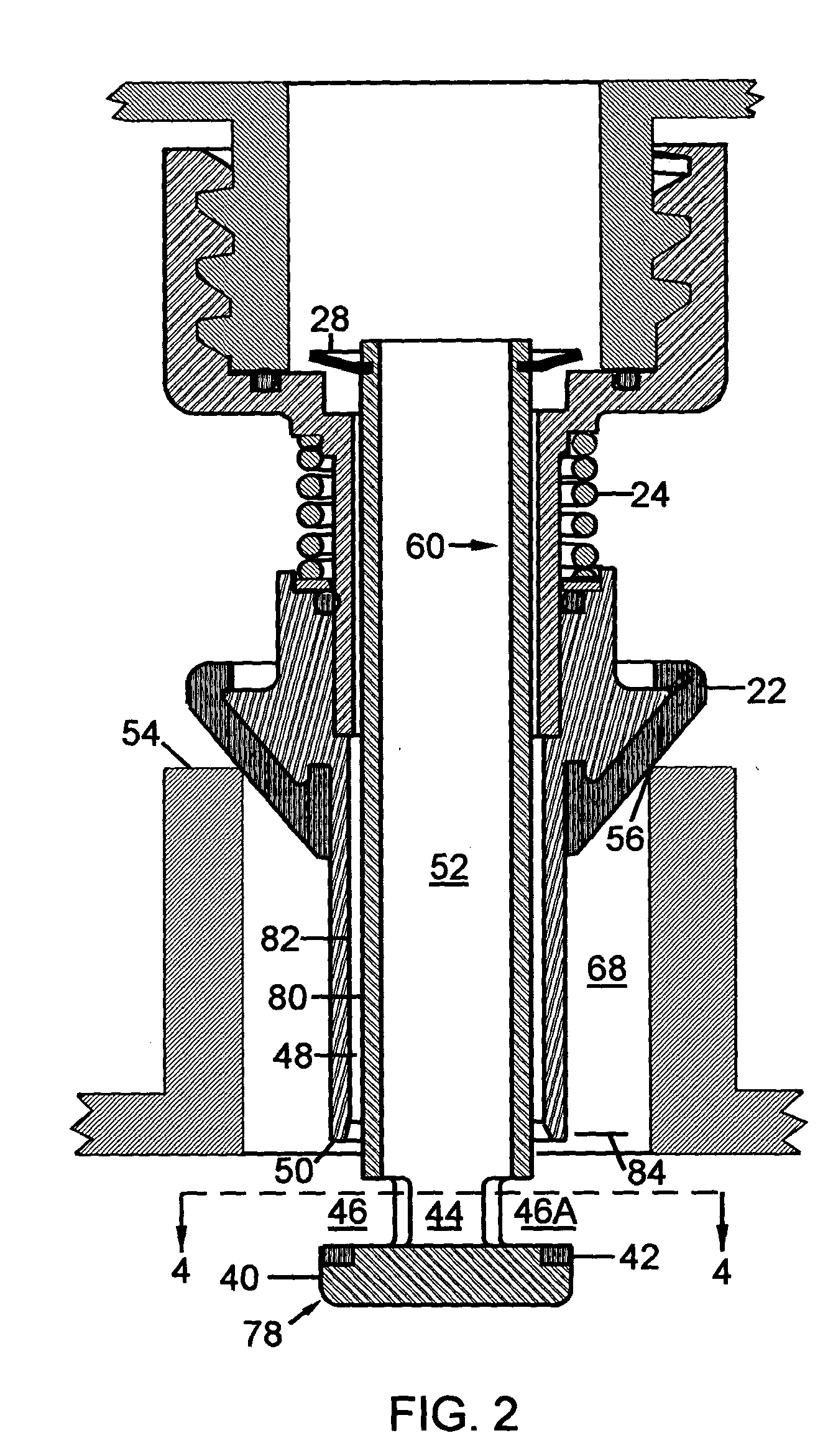
The problem arises from a combination of poor
visibility of the rising fuel level in the vehicle
fuel tank, combined with the operator's natural desire to finish the refueling as quickly as possible, while still filling the tank completely.
An increasing problem is the effect on air quality.
Spills can occur if the user does not release the valve when the tank is full and, as pointed out earlier, it is often difficult, under adverse lighting conditions, to observe the rapidly rising fuel level in the small openings found in most fuel tanks.
1. Devices which initiate the development of the partial vacuum after the fuel level reaches the vent tube entrance level can, and do, allow serious overfill
spillage when the volume of air left in the container is large. Boyle's gas law states that in a
closed system, at constant temperature, the absolute pressure of a gas, multiplied by its volume, is a constant. Application of this principle reveals that, when a gallon or more of fuel has been poured from the container, the volume of vapor and air mixture remaining in the container must be expanded as much as 5 to 8 cubic inches before a partial vacuum capable of stopping the flow of fuel is developed. This is especially true when an initial volume of vapor and air in the container, in addition to that of the poured fuel, is accounted for. This expansion requires an equal volume of fuel flow, and is a major reason why many of the prior-art devices fail to control spillage.
2. Attempts to avoid this problem by restricting the rate of vapor and air flow to the container while refueling, and thus to develop and maintain the partial vacuum during the entire time when the fuel is flowing, suffer from a different but equally annoying problem. Restriction of vapor and air flow to the container during refueling necessarily reduces the rate of fuel flow from the container. This slows refueling and is very tiring to a user holding the heavy container in an awkward position. Tests have revealed a flow rate as low as one gallon a minute with this type of device which is a burden when refueling a large garden
tractor.
3. Open-
system devices, which fail to seal the tank from the
atmosphere, allow the vapor to follow the path of least resistance and, since it is
lighter than air, it is free to move upward and out of the tank while the heavier air can move downward into the vicinity of the vent tube. This is even more likely to happen on a windy day, with the result that much of the air entering the vent tube may be
atmospheric air rather than gasoline-vapor laden air. It is axiomatic that any vapor volume which is not allowed to return to the container must escape to the
atmosphere with an open-
system, sacrificing much of the initial purpose of the device. All of the prior art devices are open-
system devices and thus fail under this criterion.
U.S. Pat. Nos. 4,834,151, 5,076,333, 5,249,611, and 5,419,378 to Law rely upon a capillary to
restrict vapor flow to the container, yet these fail to prevent spills even with the restricted vapor flow and resulting decreased fuel flow rate.
On a hot day an un-vented container of gasoline can develop a high
vapor pressure, especially if left sitting in the sun.
Obviously, this sacrifices again some of the initial purpose of the spout design.
The possibility of creating a partial vacuum within the container of warm gasoline is certainly in question, and the probability of fuel spillage is again apparent.
The problems outlined above will occur with any device which relies on a partial container vacuum to stop fuel flow, and which allows the
fuel tank opening to remain exposed to the atmosphere while refueling.
Each of the prior art devices, which claim to provide spill-proof refueling of off-road power equipment, suffers from one or more of the deficiencies described above.
1. To provide a closed and sealed system consisting of the fuel container, the spout of the present invention, and the fuel tank, wherein the fuel flow is stopped by an increase in the vapor and air pressure in the tank, rather than by a decrease in the vapor and air pressure in the container.
2. To provide a spring-biased shutoff valve to automatically contain the fuel before the spout with its tank / seal is removed from the tank opening.
3. To provide a spring-biased, cone-shaped, spout / tank seal between the tank and the atmosphere, with a cone included angle preferably less than 90 degrees, which tends to be self-centering when it is applied to the tank opening. The range of cone diameters chosen for this seal gives it the capability of sealing all of the tank openings of off-road equipment from large tractors to small string trimmers.
4. To provide a spout / tank seal surface of rubber, or a rubber-like material, sufficiently resilient to establish a reliable seal with
metal or plastic tanks used on off-road internal
combustion engines. The latter often have square edged, sometimes poorly finished surfaces, which may or may not include some nicks or scratches.
5. To provide a vapor / air passageway having generous flow capacity to allow the vapor and air mixture, which is being displaced by the rising fuel level in the tank, to flow freely into the container. This maintains the container pressure nearly equal to the
tank pressure increasing the flow rate of fuel to the tank and reducing the time required to fill the tank.
6. To provide a low flow-resistance
check valve the purpose of which is to inhibit the intrusion of fuel into the vapor / air passageway while refueling. This low flow-resistance, in addition to the low flow-resistance of the vapor / air passageway, reduces the time required fill the tank as described under object 5 above.
7. To provide a flow rate of fuel to the tank which is even greater than the flow rate of a conventional vented fuel container by ensuring that the fuel conduit to the tank will always be full-flowing. This is a maximum-flow condition, developed when the conduit is filled completely and exclusively with fuel and the total head of fuel in the container is available to maximize the flow rate. This performance can not be achieved with a conventional vented gas can, because of the lack of a means to quickly stop the flow when the tank is nearly full, and it is not available with the prior-art devices described above without risk of spillage.
8. To provide a sealed
cushion of trapped vapor and air in the tank after the rising fuel level has reached and covered the entrance to the vapor / air passageway. This
cushion of trapped vapor and air absorbs the
momentum of the rising fuel and, thereafter, maintains the static fuel level in the tank at a small fraction of an inch above the opening to the vapor / air passageway until the shutoff valve is closed with the removal of the spout with its tank seal and container.
9. To provide a biasing spring which is pre-compressed during
assembly, with sufficient force to maintain a reliable spout / tank seal isolating the tank from the atmosphere under all conditions of usage, including the surge of fuel expected with the high-temperature, container vapor pressures described above.


