Exhaust emission control method and system
- Summary
- Abstract
- Description
- Claims
- Application Information
AI Technical Summary
Benefits of technology
Problems solved by technology
Method used
Image

Examples
Embodiment Construction
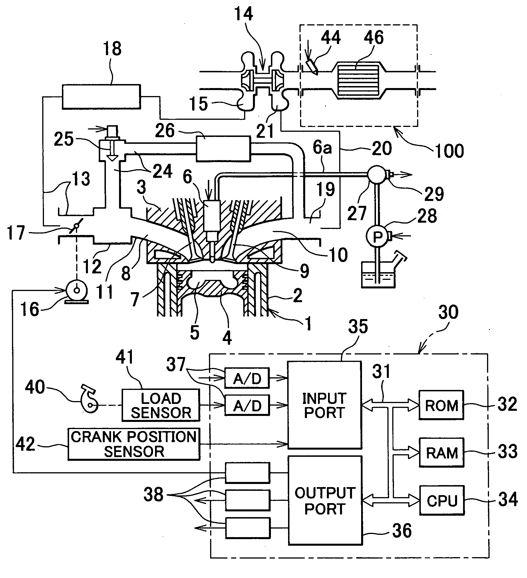
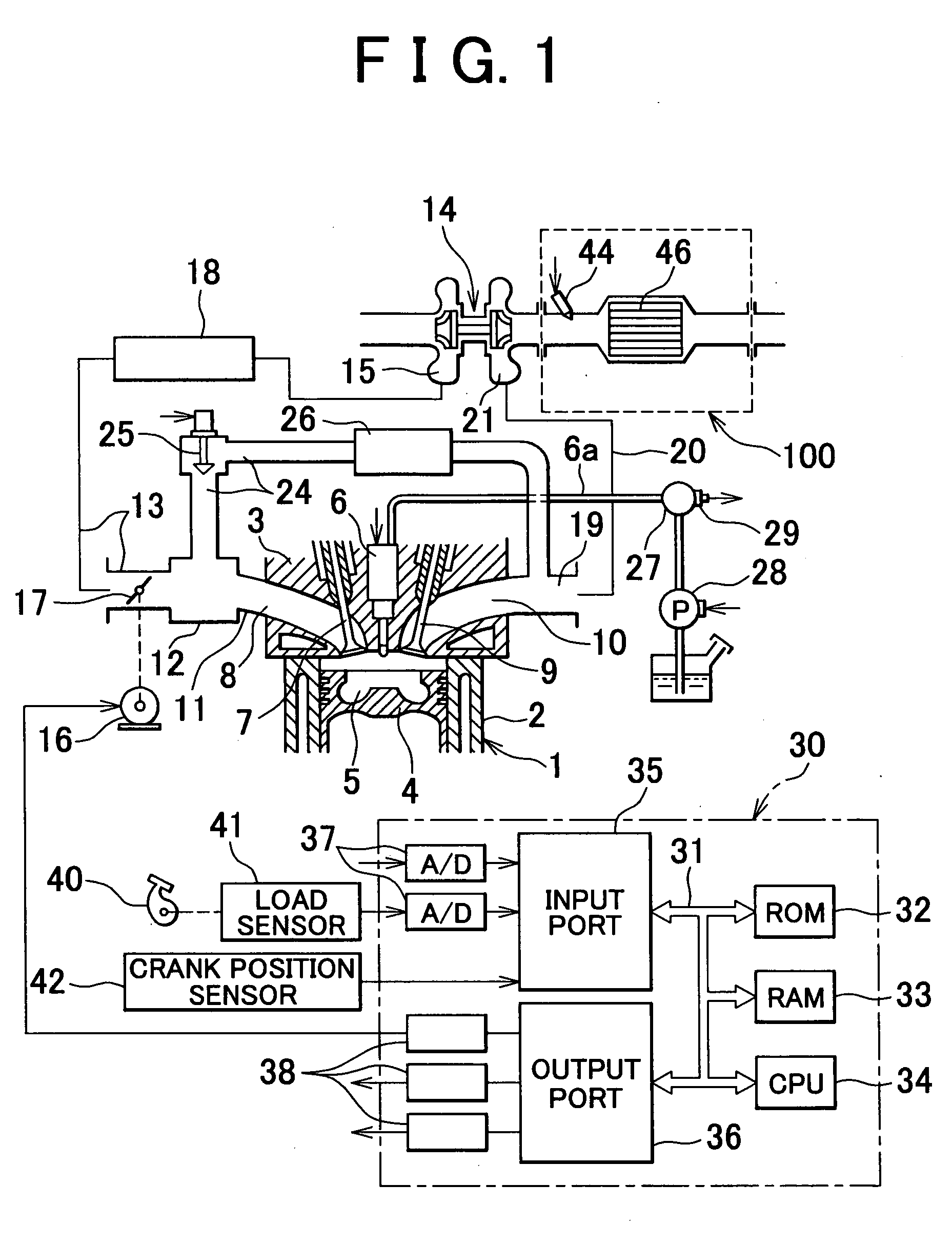
[0040] Exemplary embodiments of the invention will be described in detail with reference to the drawings. FIG. 1 shows a system in which an exhaust emission control method according to one embodiment of the invention is applied to a direct fuel injection, compression ignition type internal combustion engine. The invention may also be applied to spark ignition type internal combustion engines.
[0041] The system shown in FIG. 1 includes an engine body 1, a cylinder block 2, a cylinder head 3, a piston 4, a combustion chamber 5, an electrically controlled fuel injector 6, an intake valve 7, an intake port 8, an exhaust valve 9 and an exhaust port 10. The intake port 8 communicates with a surge tank 12 via a corresponding intake branch pipe 11, and the surge tank 12 is connected to a compressor 15 of an exhaust turbocharger 14 via an intake duct 13. A throttle valve 17 adapted to be driven by a step motor 16 is disposed in the intake duct 13, and a cooling device 18 for cooling intake ai...
PUM
 Abstract
Description
Claims
Application Information
 - R&D
- Intellectual Property
- Life Sciences
- Materials
- Tech Scout
- Unparalleled Data Quality
- Higher Quality Content
- 60% Fewer Hallucinations
Browse by: Latest US Patents, China's latest patents, Technical Efficacy Thesaurus, Application Domain, Technology Topic, Popular Technical Reports.
© 2025 PatSnap. All rights reserved.Legal|Privacy policy|Modern Slavery Act Transparency Statement|Sitemap|About US| Contact US: help@patsnap.com