
Automatic feeding and cutting device for copper bars

An automatic feeding and cutting device technology, which is applied in the direction of sawing machine devices, metal sawing equipment, metal processing, etc., can solve the problems that affect the cutting work of copper rods, high labor intensity, time-consuming and laborious, etc.

Active Publication Date: 2018-10-16
诸暨市澳格厨卫有限公司
View PDF7 Cites 9 Cited by
  • Summary
  • Abstract
  • Description
  • Claims
  • Application Information

AI Technical Summary

Problems solved by technology

Existing copper rods are all extruded, and need to be cut after forming. In the current cutting process of copper rods, most of them are cut by manually holding copper rods with saw blades. The disadvantage is that the labor intensity is high. , and during the cutting, the vibration force generated by the machine is strong, which will affect the cutting work of the copper rod, so that there are problems such as irregularity at the rear end of the copper rod cutting. Sorting, stacking and loading materials one by one into the set placement slots so that the cutting can be effectively completed, which can make this very time-consuming and laborious, and increase the cost of the manufacturer's personnel

Method used


Image

  • Automatic feeding and cutting device for copper bars
  • Automatic feeding and cutting device for copper bars
  • Automatic feeding and cutting device for copper bars

Examples


Embodiment Construction

[0025] Below in conjunction with accompanying drawing and embodiment of description, specific embodiment of the present invention is described in further detail:

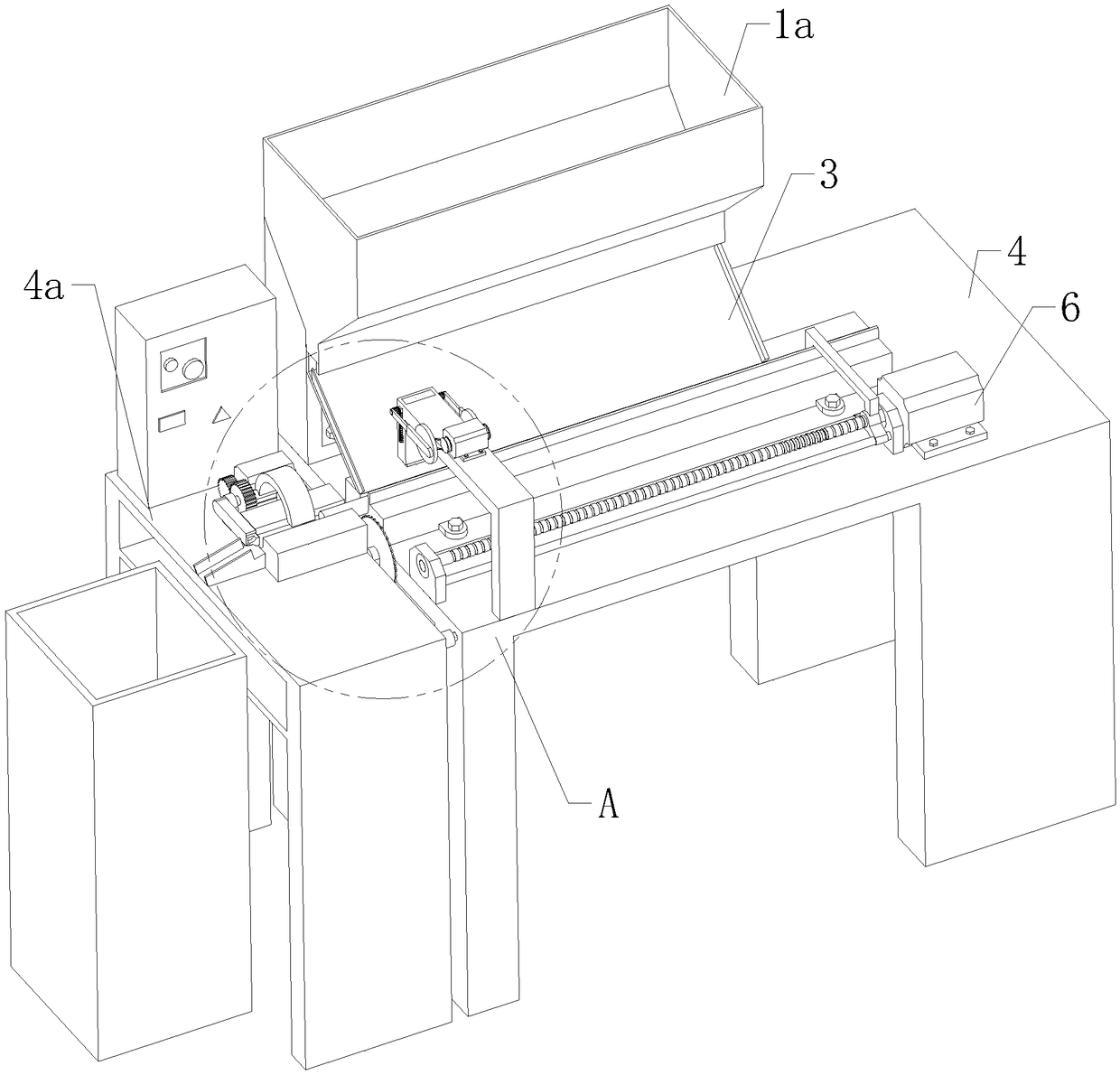
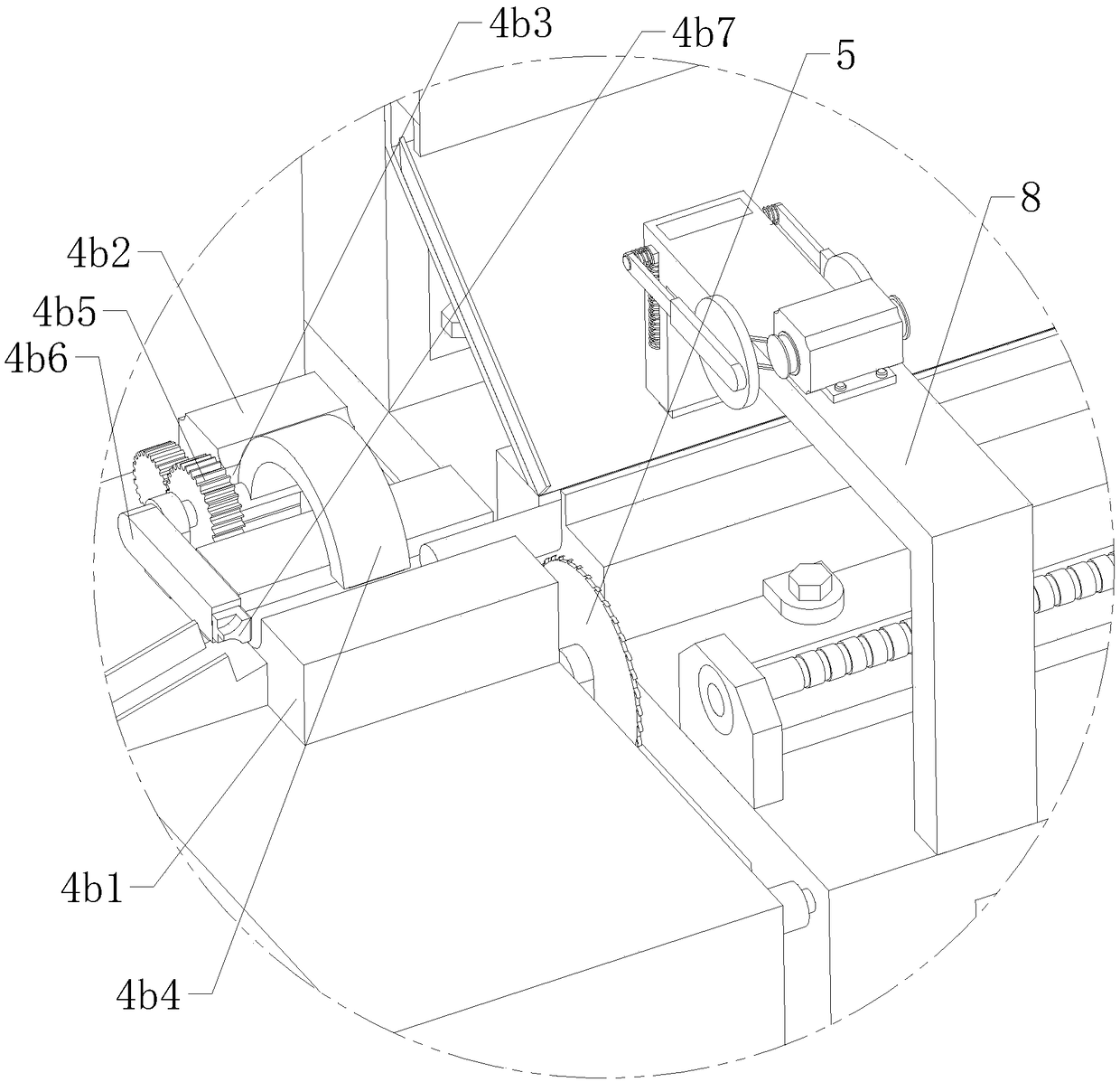
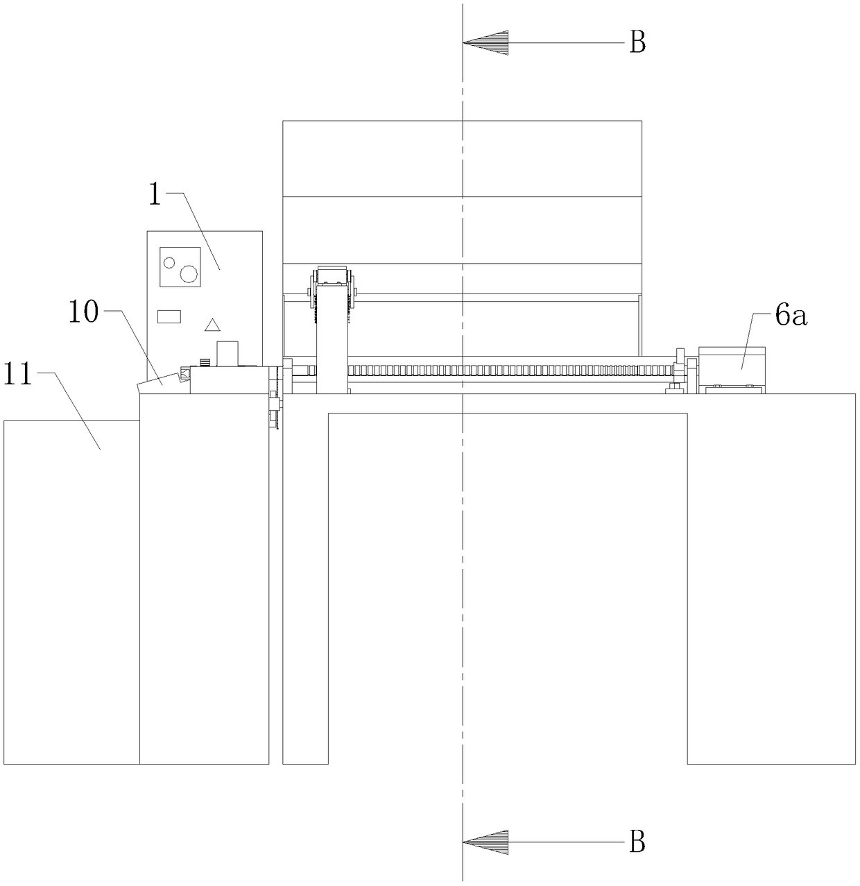
[0026] refer to Figure 1 to Figure 9 The shown automatic feeding and cutting device for copper rods includes a control cabinet 1, a feeding bin 1a, a transition assembly arranged in the feeding bin 1a, a buffer assembly 3 located at the bottom of the feeding bin 1a, and a cutting station 4 One end of the cutting station 4 is provided with a discharge table 4a, the discharge assembly is arranged on the discharge table 4a, a cutting assembly 5 is arranged between the discharge table 4a and the cutting station 4, and the top of the cutting station 4 A pusher assembly 6 is provided on one side, a blanking slideway 7 is built on the top of the cutting station 4, the buffer assembly 3 is inclined above the blanking slideway 7, and the end of the buffer assembly 3 is close to the blanking slideway 7 , the discharge assem...


PUM


Abstract

The invention relates to the field of copper bar machining, in particular to an automatic feeding and cutting device for copper bars. The automatic feeding and cutting device comprises a control cabinet, a feeding bin, a filtering assembly arranged in the feeding bin, a buffering assembly located at the bottom of the feeding bin and a cutting station table. A discharging table is arranged at one end of the cutting station table. A discharging assembly is arranged on the discharging table. A cutting assembly is arranged between the discharging table and the cutting station table. A material push assembly is arranged on the top of the cutting station table. A falling sliding way is arranged on the top of the cutting station table in a lapped manner. The buffering assembly is obliquely located above the falling sliding way. The discharging assembly comprises a diversion block right opposite to the falling sliding way, and a proximity sensor. A control cabinet is electrically connected with the proximity sensor. The end, close to the diversion block, of the falling sliding way is provided with a limiting assembly. By means of the automatic feeding and cutting device for the copper bars, the copper bars can be automatically completely conveyed into a first arc groove, the copper bars are stably moved to a to-be-cut area by means of the structure characteristics in the groove, in addition, the copper bars are effectively pressed and limited, and stability during cutting is ensured.

Description

technical field [0001] The invention relates to the field of copper rod processing, in particular to an automatic feeding and cutting device for copper rods. Background technique [0002] Copper rods are non-ferrous metal rods, made of copper, with high electrical conductivity. Wide application, mainly divided into brass rods, copper rods and so on. Existing copper rods are all extruded, and need to be cut after forming. In the current cutting process of copper rods, most of them are cut by manually holding copper rods with saw blades. The disadvantage is that the labor intensity is high. , and during the cutting, the vibration force generated by the machine is strong, which will affect the cutting work of the copper rod, so that there are problems such as irregularity at the rear end of the copper rod cutting. Sorting, stacking and feeding one by one into the set placement slots so that the cutting can be effectively completed can be very time-consuming and labor-intensiv...

Claims


Application Information

Patent Timeline
Patent Type & Authority Applications(China)
IPC IPC(8): B23D47/04B23Q7/10
CPCB23D47/04B23D47/042B23Q7/10
Inventor 文丹
Owner 诸暨市澳格厨卫有限公司
Learn More