
Method and device for producing an optically antireflective surface

a technology of anti-reflective surface and optical surface, which is applied in the direction of microlithography exposure apparatus, mirrors, instruments, etc., can solve the problems of hemispherical reflection, i.e., the most favorable case of increased hemispherical reflection, and achieve the effect of improving the achievable exposure results

Inactive Publication Date: 2004-02-05
FRAUNHOFER GESELLSCHAFT ZUR FOERDERUNG DER ANGEWANDTEN FORSCHUNG EV
View PDF3 Cites 9 Cited by
  • Summary
  • Abstract
  • Description
  • Claims
  • Application Information

AI Technical Summary

Benefits of technology

[0015] A key element of the present invention is that a method for producing a surface structure which is antireflective for a certain wavelength range, which has the smallest wavelength limit .lambda..sub.M, having a supporting coat on which a coat of a light-sensitive material is applied which is exposed to at least two mutually coherent wave fields with a wavelength of .lambda..sub.B in order to obtain a stochastically distributed interference field, whereby during or after exposure, the surface structure is formed by means of selective removal, is improved in such a manner that the mutually interfering, coherent wave fields directed at the coat of light-sensitive material form an angle .alpha., with.alpha.>2 arcsin(.lambda..sub.B / (2.multidot..lambda..sub.M)).
[0017] Preferably, at least one of the mutually interfering, coherent wave fields has a stochastic amplitude and phase distribution. The more wave fields, whose amplitudes are preferably equally large, impinge upon the coat of light-sensitive material at the above angle relationship, the better the achievable exposure results.
[0024] The surface structures produced in this manner can be replicated using prior art replication processes, for example using drum imprinting methods, die imprinting methods or injection molding processes. The advantage of these processes is that structured surfaces can be inexpensively produced. All these methods can be easily applied as in the invented stochastic surface structure there is no under cutting. Galvanically produced matrixes can be used as an imprinting die or tool for large surface replication of microstructures. In this manner, many imprinting dies can be obtained in an advantageous way from one single original surface structure by means of recopying. Alternatively, a structure can also be applied in a die by means of an etching process.

Problems solved by technology

The reflex phenomena occurring on the interfaces of transparent media impair the transparency properties as well as the readability of display screens or displays considerably.
However, a disadvantage of this type of dereflection is that the hemispherical reflection, i.e. the sum of mirroring and diffuse reflection into the entire rear part of the room, is in the most favorable case not increased.
The structure of the interference coat is designed in such a manner that, in suited wavelength ranges, destructive interference phenomena occur in the reflected radiation field, thereby greatly reducing the brightness of, for example reflexes of light sources.
However, contrary to the aforementioned anti-glare coat, their imaging in the reflected radiation path remains sharp.
For most display screens and other applications, however, interference coats are too expensive in production.
However, large-surface production of such types of structures is very difficult due to only very narrow optical tolerance ranges with regard to the variance of structure depths and a very high aspect ratio, i.e. very high ratio of structure depth to structure period, which can lead to falsifying color effects.
Although both methods permit replication of the obtained stochastic surface structures by means of prior art imprinting processes, the surface structures obtained using these methods have the drawback that the angle at which residual light is reflected back cannot be selectively set (e.g. small-angle scattering or scattering into a large solid angle).

Method used


Image

  • Method and device for producing an optically antireflective surface
  • Method and device for producing an optically antireflective surface

Examples


Embodiment Construction

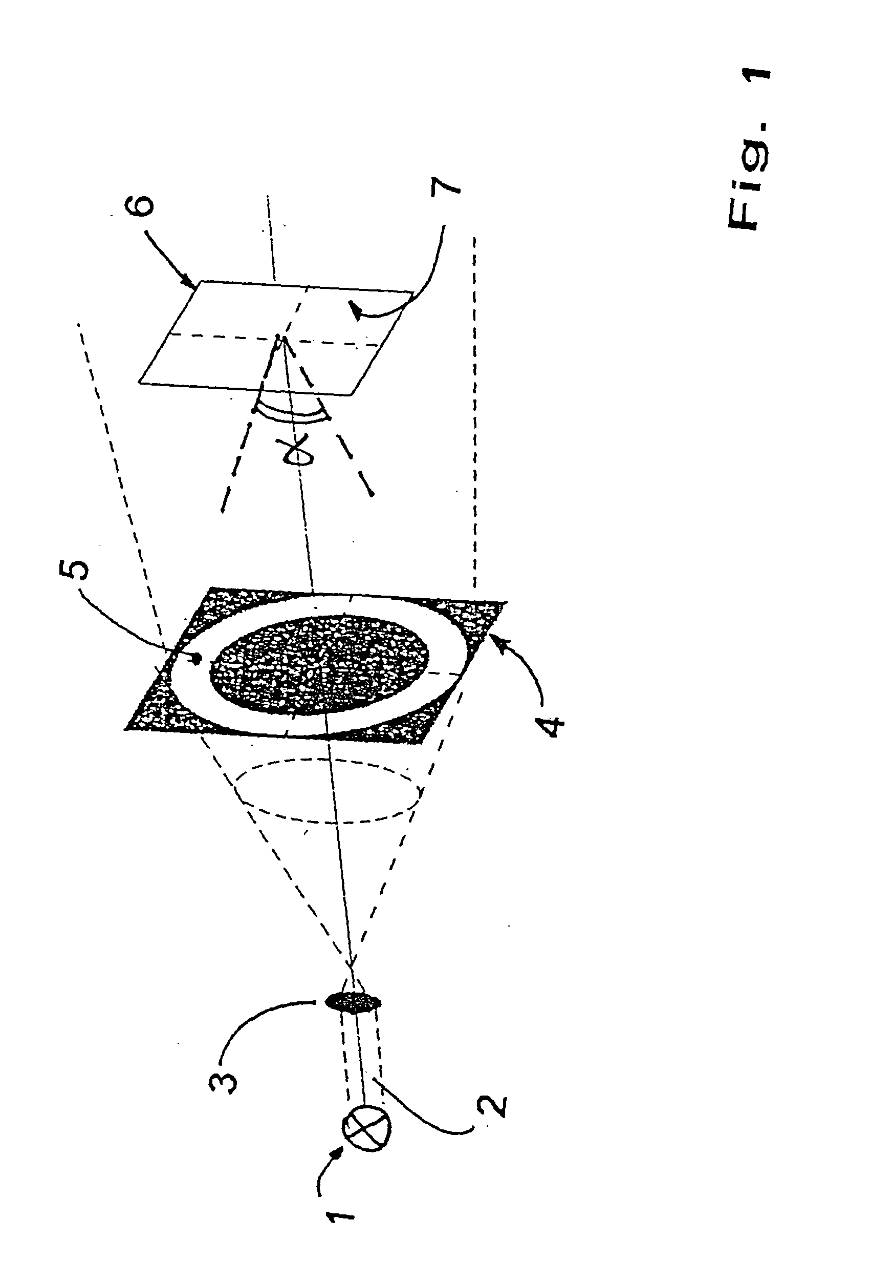
[0029] FIG. 1 shows an radiation setup having a light source 1, preferably an excimer laser, for example an Ar-ion laser, which emits a coherent light beam 2. A lens 3, which widens the light beam 2 to a diffuser unit 4 which provides an optically diffuse acting, transparent ring region 5 and is otherwise designed opaque, is provided in the beam path downstream of the light source. In the beam path downstream of the diffuser unit 4, a supporting plate 6 is provided on which a photoresist coat 7 is applied.

[0030] The single waves coming from the diffuser unit 4 interfere on the side facing away from the light source in such a manner that partial waves from opposite sectors of the diffuser unit, preferably designed as a ring diffuser, form a large angle .alpha., determined by the geometric measurements of the ring region 5 and the distance between the diffuser unit 4 and the supporting plate 6. Due to the given geometry, mainly light waves impinge upon the photoresist coat 7, which fo...


PUM

PropertyMeasurementUnit
transparentaaaaaaaaaa
Wavelengthsaaaaaaaaaa
angleaaaaaaaaaa

Abstract

Disclosed is a method for producing a surface structure which is antireflective for a wavelength range with a minimal wavelength lambdaM, having a supporting coat on which a light-sensitive material is applied which is exposed with at least two mutually coherent wave fields with a wavelength of lambdaB in order to obtain a stochastically distributed interference field, whereby during or after exposure, said surface structure is formed by means of selective removal of materials. The invention is distinguished by mutually interfering, coherent wave fields directed at the light-sensitive coat of material forming an angle alpha, for which applies: alpha>2 arcsin(lambdaB / (2.lambdaM))

Description

[0001] 1. Field of the Invention[0002] The present invention relates to a method and a device for producing an optically antireflective surface structure (e.g. for visible light) having a supporting coat on which a coat of light-sensitive material is applied, which is exposed to at least two mutually coherent wave fields with a wavelength of .lambda..sub.B in order to obtain a stochastically distributed interference field, whereby during or after exposure, the surface structure is formed by means of selective removal of material.[0003] 2. Description of the Prior Art[0004] At the interfaces of transparent media, such as for example glass or plastic panes, which are preferably used for windows, display screens or display surfaces of instruments, always one part of the incident light falling on the interface surfaces is reflected thus reflected back into the space from where the light comes. The reflex phenomena occurring on the interfaces of transparent media impair the transparency ...

Claims


Application Information

Patent Timeline
Patent Type & Authority Applications(United States)
IPC IPC(8): G02B1/11G03F7/20
CPCG02B1/11
Inventor BLSI, BENEDIKTKUBLER, VOLKERGOMBERT, ANDREASBOERNER, VOLKMAR
Owner FRAUNHOFER GESELLSCHAFT ZUR FOERDERUNG DER ANGEWANDTEN FORSCHUNG EV
Learn More