Optical recording medium

a technology of optical recording and optical tape, applied in optical recording/reproducing/erasing methods, instruments, photomechanical equipment, etc., can solve the problems of inability to obtain excellent reproduction characteristics by such measures as modifying the depth of recessed portions, and the slope of the side walls of the groove, so as to achieve excellent reproduction characteristics and high reproduction output.

Inactive Publication Date: 2004-01-15
SONY CORP
View PDF8 Cites 9 Cited by
  • Summary
  • Abstract
  • Description
  • Claims
  • Application Information

AI Technical Summary

Benefits of technology

[0014] According to the present invention, in an optical recording medium of the above mentioned write once type optical recording medium currently so-called next generation optical recording medium in which wavelength of the irradiated reproduction light is made shorter and the reproduction light is irradiated onto a recording surface from the side of a light transmissive protection film, there is provided such optical recording medium as capable of obtaining high reproduction output and having excellent reproduction characteristics.

Problems solved by technology

However, there is a problem when knowledge of the conventional write once type CD-R and DVD-R is applied to the write once type optical recording medium (DVR) employing the above-mentioned short wavelength and high N.A.
Specifically, in an optical recording medium using a short wavelength of 380 nm.about.450 nm, e.g., blue-violet light source of 405 nm.+-.5 nm for high recording density, i.e., high resolution, if the recording film is comprised of organic pigment material, the characteristics of such organic pigment material constituting the recording film differ from those in CD-R and DVD-R and optical characteristics and optical conditions may be different, so that there may be problems in applying knowledge used in general CD-R and DVD-R.
For example, it is impossible to obtain excellent reproduction characteristics by such measures as modifying depth of recessed portions, for example, tracking grooves formed in the substrate of an optical recording medium in response to differences in wavelengths of irradiated lights.
However, when such fine track pitches as those provided in the above mentioned DVR are narrow and small, the pattern exposure by the above mentioned light results in gentle slope of side walls of the grooves.
Accordingly, although there have been attempted such methods as performing pattern exposure onto the photoresist by electron beam lithography, by reducing a spot size with disposing a focusing lens adjacent to the exposure surface in an optical system, i.e., taking so-called near field construction or the like in order to sharpen the side walls of the grooves or to improve those conditions, studies on optimization of the side walls of the grooves are insufficient, and sufficient reproduced output has not yet been achieved.

Method used


Image

  • Optical recording medium
  • Optical recording medium
  • Optical recording medium

Examples


first embodiment

[0070] [First Embodiment]

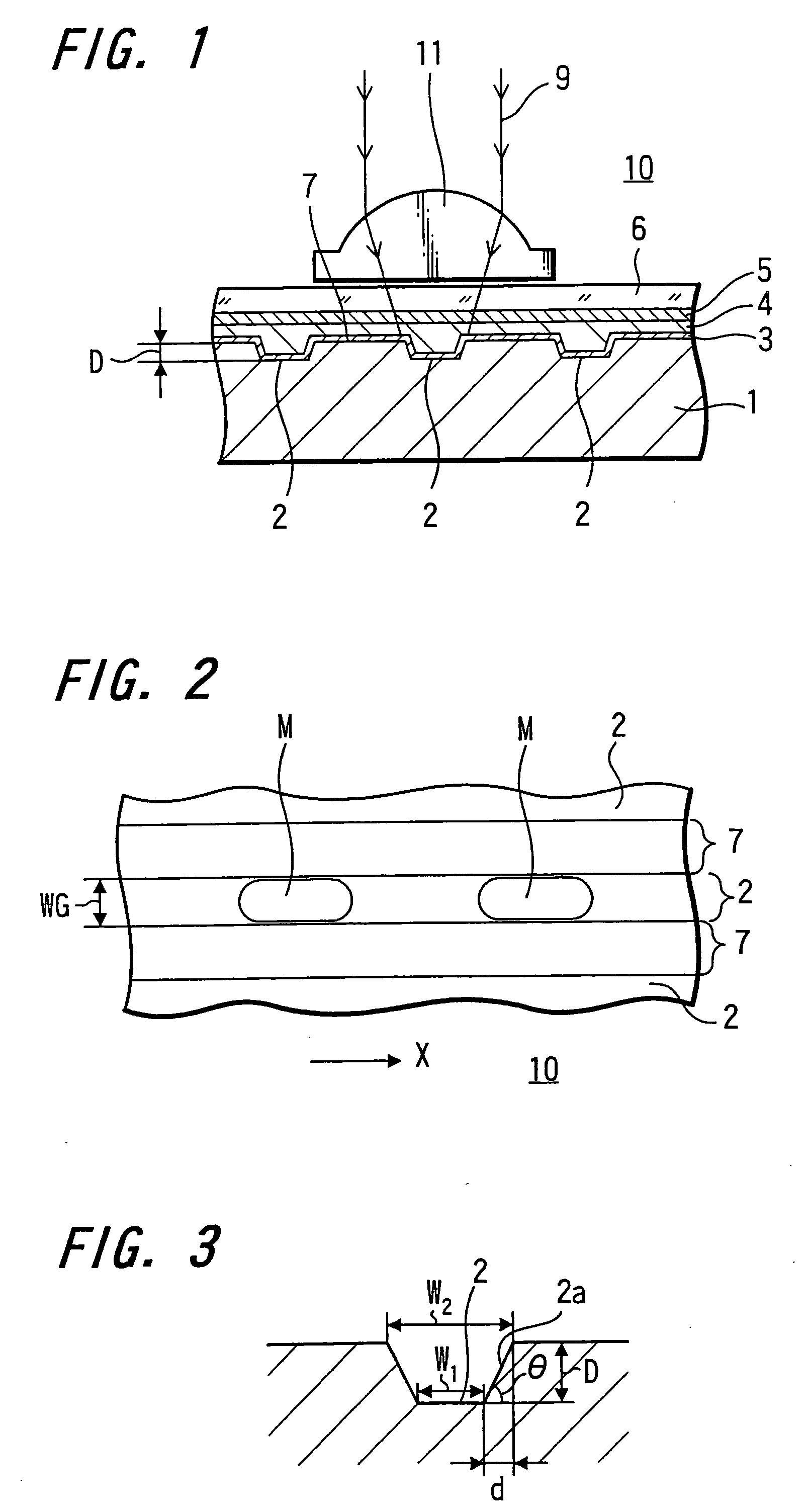
[0071] In this embodiment, the recessed portions 2 are grooves provided as tracking guide grooves having the dimensions of 100 nm in depth, 0.12 .mu.m in width, 0.6 .mu.m in space between the grooves, and tan.theta.=2 in slope of the side walls of the grooves as illustrated in FIG. 3.

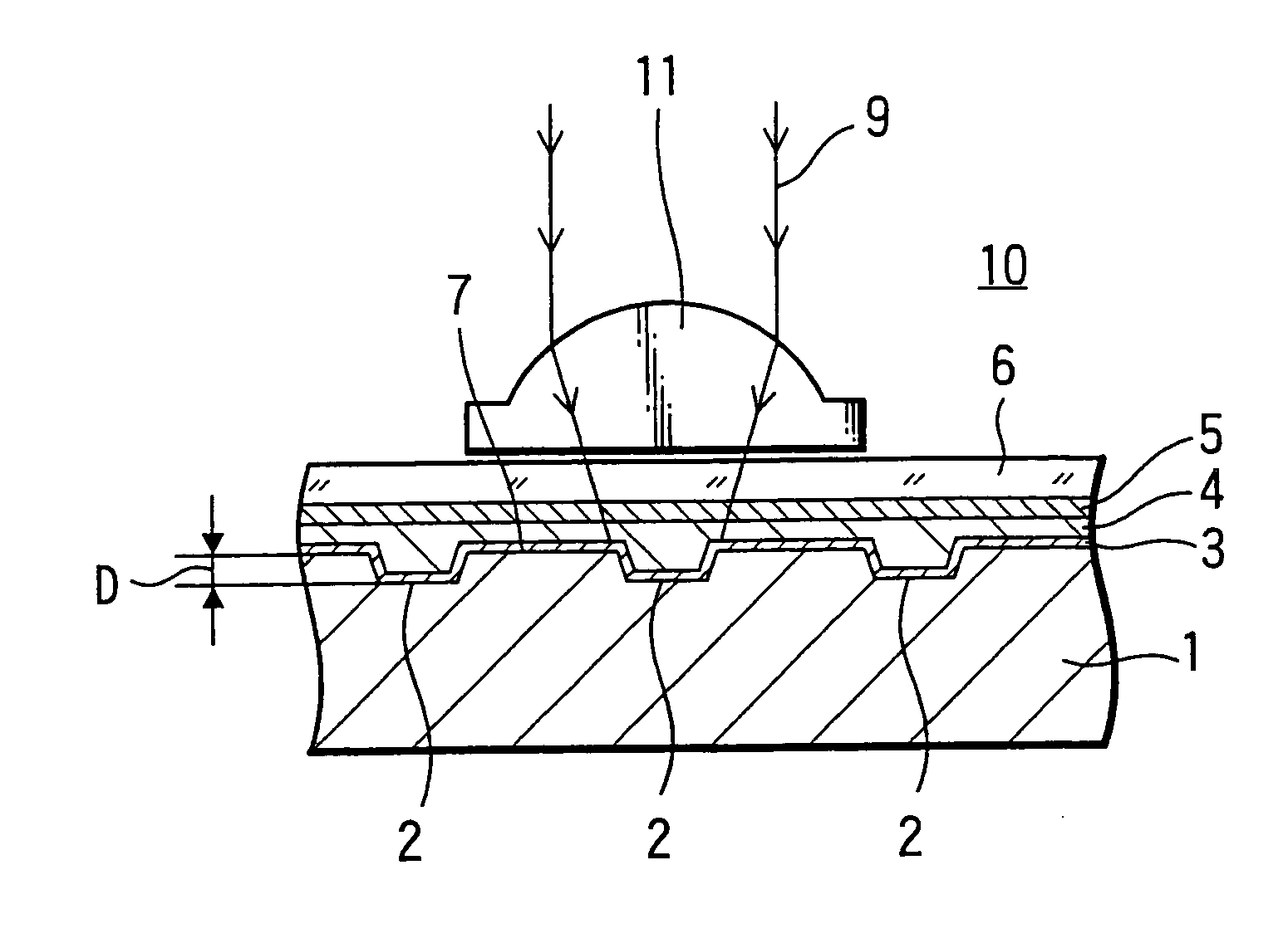
[0072] Also, in this embodiment, a phase modulation type optical disc is manufactured using a polycarbonate (PC) substrate 1 in which the recessed portions 2, i.e., the grooves are formed in one main surface of the substrate 1, the metal film 3 is formed by sputtering Ag of 20 nm in thickness on the surface where the grooves are formed, and the recording film 4 of an organic pigment film, the dielectric film 5 made from SiN of 10 nm in thickness and the light transmissive protection film 6 are sequentially formed on the metal film 3.

[0073] The organic pigment film is formed by spin coating. In this case, thickness of the film is set to 170 nm inside the grooves and 70 nm on the ...

second embodiment

[0083] [Second Embodiment]

[0084] FIG. 8 shows measurement results of respective reproduction signal amplitude, i.e., the returned light amounts obtained by changing the width of the groove in the optical recording medium according to the first embodiment. As shown in FIG. 8, the signal amplitude declines when the width of grooves exceeds a certain value. The reason for that is when width of the grooves thus increases as compared to that of the marks, the proportion of width of the marks within a spot of the reproduction light increases as the reproduction light spot comes to the center of the mark and the reflectance increases as a result of decreased interference with the land portions.

[0085] Specifically, FIG. 9 shows a reproduction signal level in the direction of grooves length when width of the grooves is increased to 0.28 .mu.m. According to FIG. 9, the reflectance increases near the center of the marks.

[0086] According to FIG. 8, it is understood that the optimum result is ob...

third embodiment

[0092] [Third Embodiment]

[0093] In the third embodiment, similarly to the first embodiment a phase modulation type optical disc is manufactured by employing the substrate 1 using polycarbonate (PC) in which grooves are formed as the recessed portions 2 and side walls are substantially vertical, forming the metal film 3 by sputtering Ag of 20 nm in thickness on the surface where the grooves are formed, and sequentially depositing thereon an recording film 4 formed of organic pigment film, the dielectric film 5 formed of SiN of 10 nm in thickness and the light transmissive protection film 6.

[0094] With respect to width of the grooves of the recessed portions 2 in the substrate, in order to obtain the above mentioned advantageous effect, width of the recessed portions 2, i.e., width of the grooves was set to 0.14 .mu.m in this embodiment. Further, width of the lands was set to be equal to the width of the grooves. The object lens was N.A.=0.85.

[0095] Further, in this embodiment, there ...


PUM

PropertyMeasurementUnit
widthaaaaaaaaaa
widthaaaaaaaaaa
widthaaaaaaaaaa

Abstract

A phase modulation type optical recording medium has at least one layer of recording film 4 and at least one layer of metal film 3 on a substrate 1 having recessed portions formed therein, wherein one or more layers constituting the recording film include organic material that decomposes upon absorption of laser light to change its refractive index, and width of the recessed portions 2 is set to 0.10 mum-0.21 mum, thereby providing an optical recording medium of write once type with high recording density capable of high reproduction output.

Description

[0001] The present invention relates to an optical recording medium, specifically to a phase modulation type optical recording medium having excellent reproduction output characteristics, in which reproduction of recorded portions is performed by irradiating light in the range of 380 nm.about.450 nm in wavelength .lambda. and organic pigment material is used as a recording film.[0002] Functional organic pigment material is heretofore widely used as recording material for write once type optical discs and are manufactured in large quantity at a low cost, particularly as write once type compact discs (CD-R).[0003] Also, in optical systems in DVD (Digital Versatile Disc), a write once type has been standardized as a write once type DVD-R and has been on sale.[0004] Moreover, as an optical disc of currently so-called a next-generation optical recording medium in which higher recording capacity, i.e., higher recording density is intended, there has been considered standardization of irra...

Claims


Application Information

Patent Timeline
Patent Type & Authority Applications(United States)
IPC IPC(8): B32B3/02G11B7/0045G11B7/005G11B7/007
CPCG11B7/00451G11B7/24079G11B7/2472Y10T428/21G11B7/259G11B2007/2571G11B2007/25713G11B7/2534G11B7/246
Inventor SABI, YUICHI
Owner SONY CORP
Why Eureka
Try Eureka