
Radiating member,illuminating device, electro-optical device, and electronic device

a technology of electrooptical devices and radiation members, which is applied in the direction of incadescent cooling arrangements, lighting and heating devices, instruments, etc., can solve the problems of reducing the temperature of the point light source, high temperature of the led, and the limitation of the brightness of the led

Inactive Publication Date: 2004-01-08
SEIKO EPSON CORP
View PDF9 Cites 80 Cited by
  • Summary
  • Abstract
  • Description
  • Claims
  • Application Information

AI Technical Summary

Benefits of technology

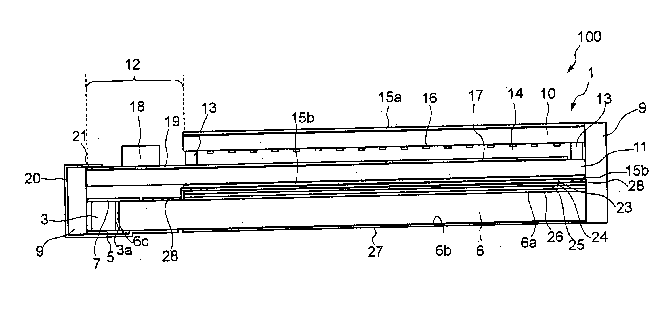
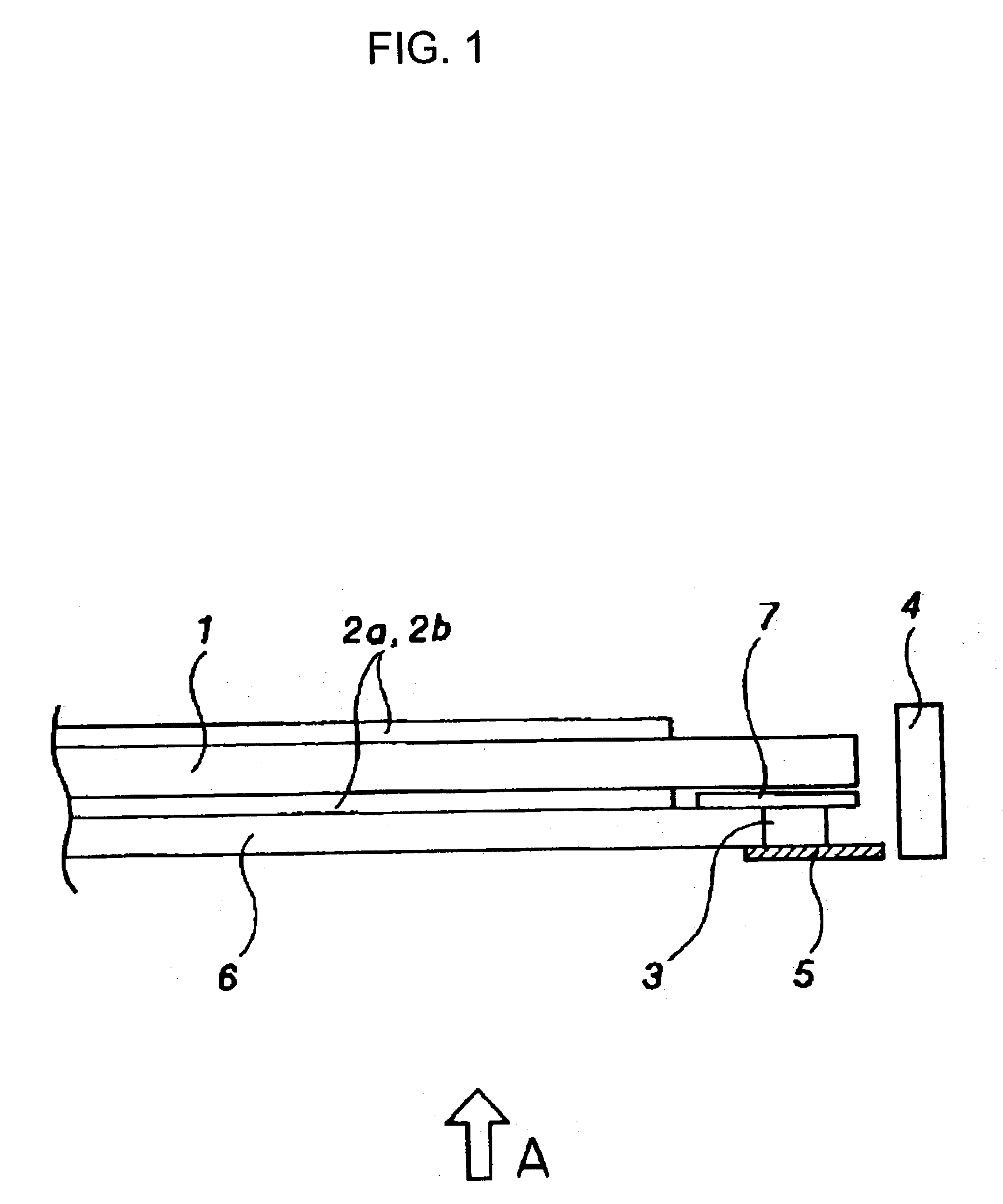
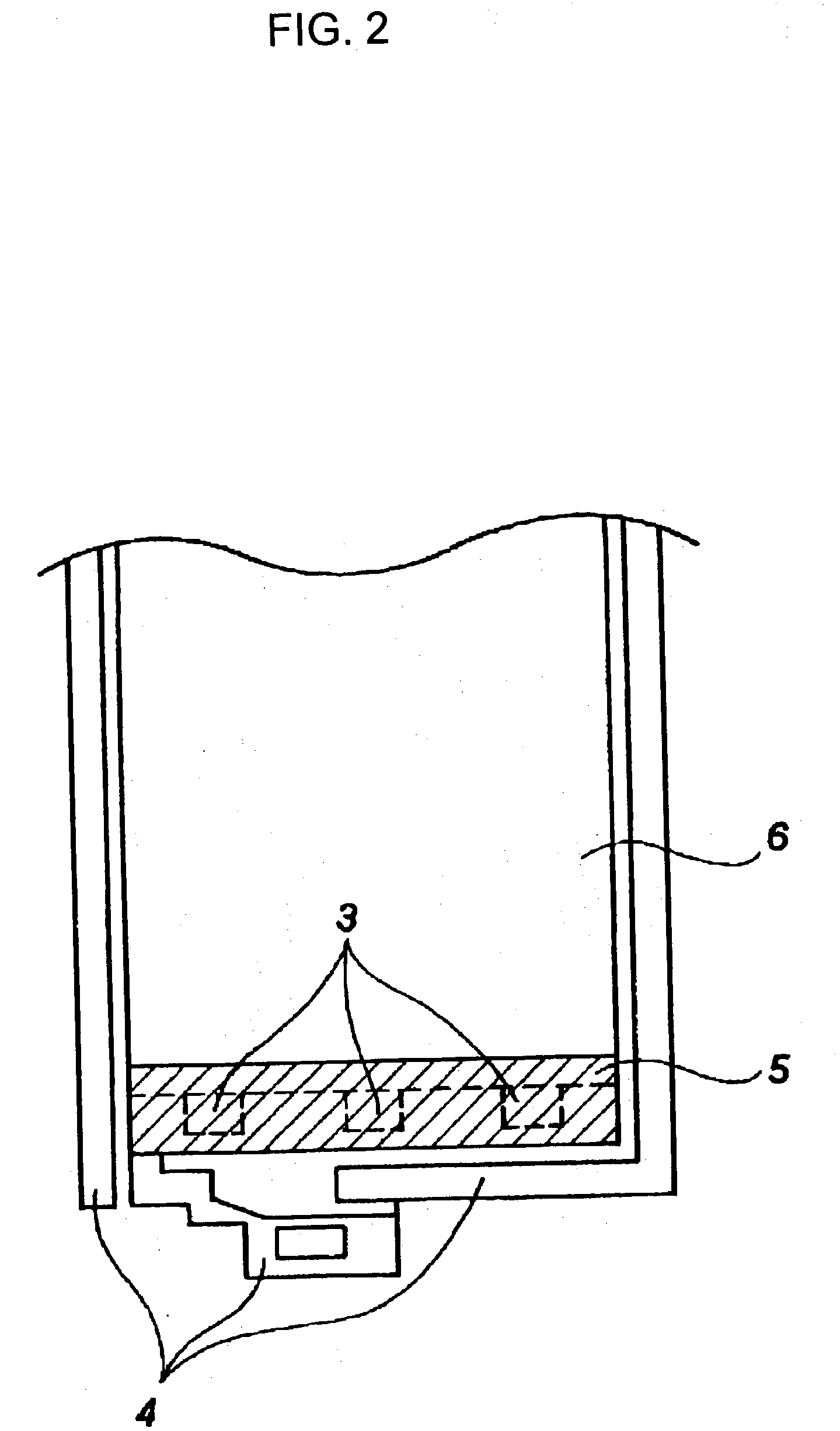
[0009] According to the above configuration, the radiating member possibly contacts and is fixed to the point light source by the adhesive layer. This will radiate the heat generated from the point light source when emitting light by the metal layer having a high thermal conductivity, thus decreasing the temperature on the point light source. Since more electric current is allowed to flow through the point light source with decreased temperature, it is possible to improve the brightness of the point light source.
[0065] According to the above configuration, the contrast of the driving region of the electro-optical panel is improved by the light-shielding of a region other than the driving region, and the brightness can be also increased because of the installation of the light-shielding radiating plate.

Problems solved by technology

However, in the above-described liquid crystal device, when electric current flows through the LED, thus causing the LED to emit the light, the temperature in the LED is high.
Therefore, there is a limitation in increasing the brightness of the LED by increasing the electric current through the LED.
This will result in decrease the temperature on the point light source.

Method used


Image

  • Radiating member,illuminating device, electro-optical device, and electronic device
  • Radiating member,illuminating device, electro-optical device, and electronic device
  • Radiating member,illuminating device, electro-optical device, and electronic device

Examples


Embodiment Construction

[0280] Embodiments of Electronic Device

[0281] Finally, there will be described on the embodiments in which a liquid crystal device including the LCD 1 as above is used as a display in an electronic device. FIG. 23 is a schematic representation showing the overall configuration of the embodiments of the present invention. The electronic device described here includes an LCD 200 the same as the above, and control means 1200 for controlling the LCD. Here, the LCD 200 is represented by conceptually divided into a panel structure 200A and a driving circuit 200B including a semiconductor IC, for example. In addition, the control means 1200 includes a display information output source 1210, a display processing circuit 1220, a power circuit 1230, and a timing generator 1240.

[0282] The display information output source 1210 includes a memory having ROM (Read Only Memory) or RAM (Random Access Memory), for example., a storage unit having an electromagnetic record disk or an optical record di...


PUM


Abstract

A radiating member, an illuminating device, an electro-optical device, and an electronic device are provided which are capable of absorbing the heat generated from an LED, thereby increasing the amount of electric current flowable through the LED. More particularly, there are provided a point light source, a light guide plate for receiving the light radiated from the point light source, and a radiating plate including an adhesive layer formed to contact the point light source, and a metal layer formed over the adhesive layer and made of the material having a thermal conductivity (lambda) equal to or greater than 90 W / mK at room temperature.

Description

[0001] 1. Technical Field of the Invention[0002] The present invention relates to an illuminating device and an electro-optical device, wherein a radiating member is disposed corresponding to a point light source.[0003] 2. Description of the Related Art[0004] Generally, a liquid crystal device, which is one example of an electro-optical device, mainly includes a liquid crystal panel and a backlight for radiating light onto the liquid crystal panel. The liquid crystal panel is formed such that a liquid crystal layer is interposed between a facing substrate and a TFT array substrate. The backlight, particularly a side light-type backlight, mainly includes a light guide plate, disposed adjacent to the liquid crystal panel and having almost the same size as the liquid crystal panel, and an LED (light-emitting device) disposed at the end of the light guide plate. The light guide plate is used to guide the light from the LED and diffused the light, and the light diffused by the light guid...

Claims


Application Information

Patent Timeline
IPC IPC(8): F21S2/00F21V8/00F21V29/00F21Y101/02G02B6/00G02F1/13G02F1/1333G02F1/13357H01J61/52H01K1/58
CPCG02B6/0066G02B6/0085G02F1/133308H01K1/58G02F1/13452G02F2001/133628H01J61/52G02F1/133615G02F1/133628G02F1/1335
Inventor SAKURAI, SHINJI
Owner SEIKO EPSON CORP
Learn More