
Generation of trace signals within a data processing apparatus

a data processing apparatus and trace signal technology, applied in the direction of detecting faulty computer hardware, specific program execution arrangements, transmission, etc., can solve the problem of increasing the complexity of processing systems, unable to track the state of processor cores via externally accessible pins, and potentially a very large amount of information that could be traced

Active Publication Date: 2003-12-11
ARM LTD
View PDF4 Cites 46 Cited by
  • Summary
  • Abstract
  • Description
  • Claims
  • Application Information

AI Technical Summary

Benefits of technology

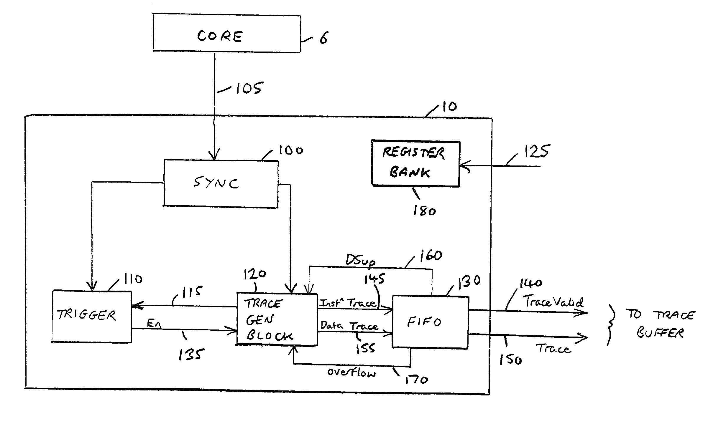
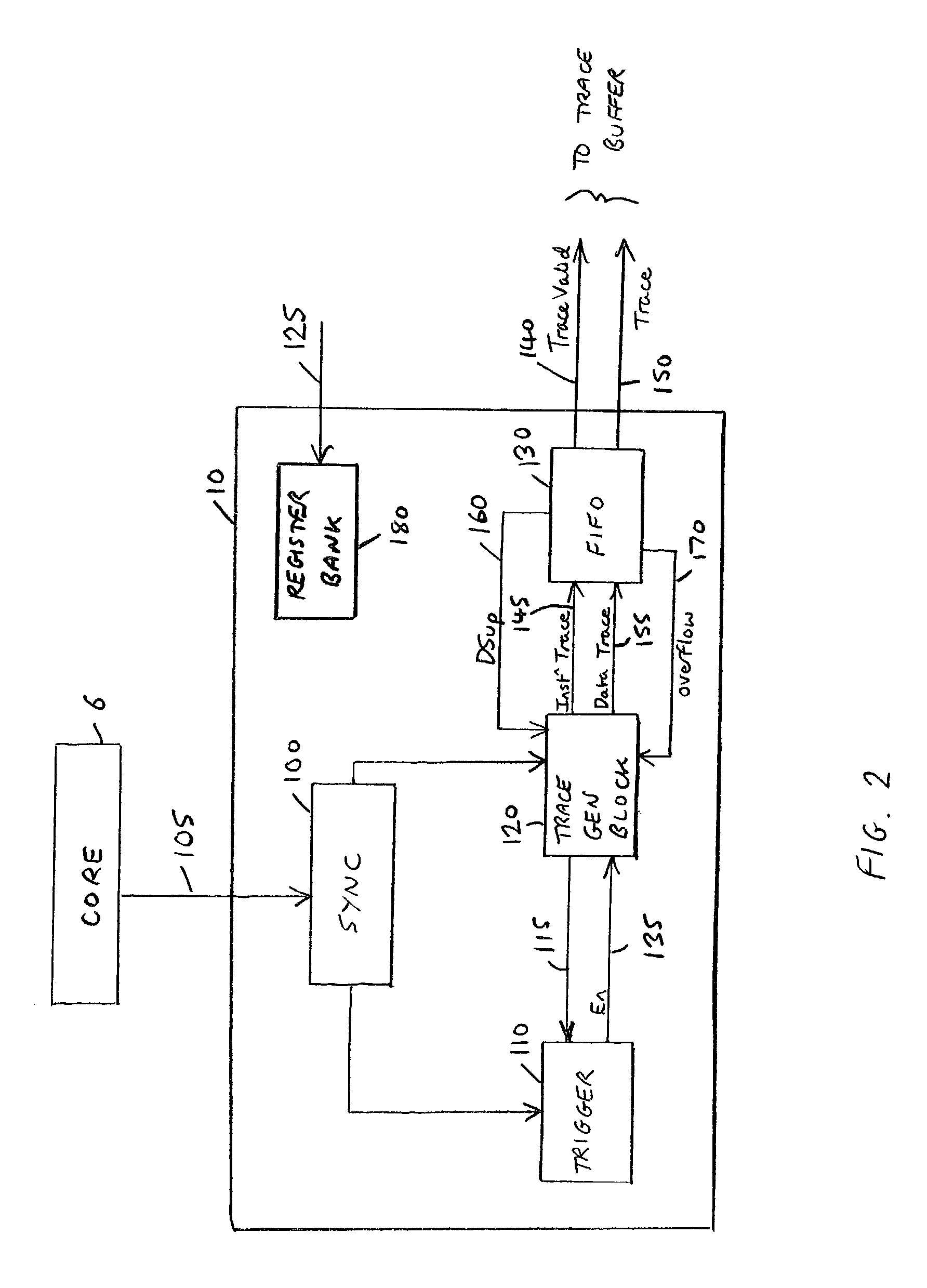
[0012] With this is mind, the data processing apparatus of the present invention is arranged to cause suppression of the low priority trace signals when deemed necessary by the trace receiving device, this hence alleviating the above described problem of the prior art, whereby the trace receiving device might overflow, leading to an arbitrary loss of trace data. Instead, in accordance with the present invention, if the trace receiving device deems it appropriate, it can issue a suppression signal to the trace generation unit to ensure that only the high priority trace signals are output, thereby significantly reducing the likelihood that the trace receiving device will overflow.
[0039] In preferred embodiments, the stalling buffer is arranged to issue the request signal when the amount of trace signals stored within the stalling buffer reaches a predetermined level. By appropriate choice of the predetermined criteria applied by the funnel logic to determine which trace module should provide trace signals to the funnel logic at any particular point in time, and by restricting the number and bandwidth of the elements interfacing with the funnel logic, it can be ensured that a stalling buffer will receive a grant signal before it overflows with trace data output by the associated trace module.

Problems solved by technology

However, with the general move towards more deeply embedded processor cores, it becomes more difficult to track the state of the processor core via externally accessible pins.
However, as data processing systems increase in complexity, it is clear that there is potentially a very large amount of information that could be traced.
Typically the stream of trace data that is generated by the ETM is buffered prior to output for subsequent analysis, and accordingly there is the potential for bursts of trace data to cause that buffer to overflow, thereby resulting in loss of trace data.
When a broad spectrum of behaviour of the data processing apparatus is being traced, it is possible that bursts of trace data can cause the FIFO to overflow, leading to loss of trace data.
However, the use of such a signal has proved difficult to implement in practice, since it requires action to be taken externally to the ETM (i.e. by the component being traced) to seek to avoid overflow of the FIFO.
A single trace module, including a single trace generation unit, may no longer be sufficient, since in such future systems there may be multiple components each requiring their behaviour to be traced.
However, it is envisaged that the cost of providing external pins, or trace buffers, for each trace module is likely to be too high.
However, it may not be appropriate simply to share pins, or a trace buffer, between multiple trace modules, since different parts of the data processing apparatus will interact, and therefore need to be traced at the same time in order to be debugged.
Accordingly, another problem to be solved is how to enable the trace signals from multiple trace modules of a data processing apparatus to be effectively traced.
However, in alternative embodiments, one or more of the trace modules may not be arranged to issue such request signals, or may not be responsive to grant signals, for example because that trace module may be a legacy design of trace module which is arranged merely to output its trace stream as and when it determines it appropriate.

Method used


Image

  • Generation of trace signals within a data processing apparatus
  • Generation of trace signals within a data processing apparatus
  • Generation of trace signals within a data processing apparatus

Examples


Embodiment Construction

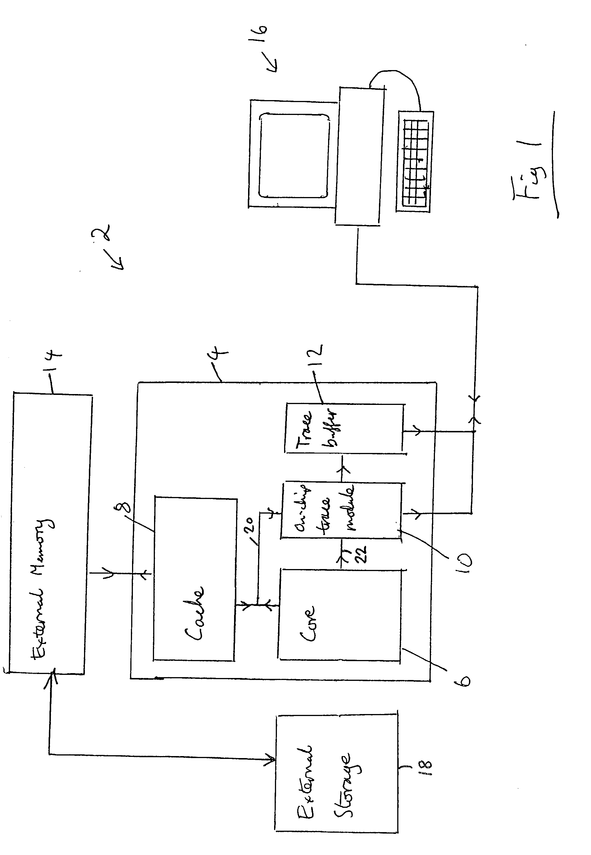
[0052] FIG. 1 schematically illustrates a data processing system 2 providing an on-chip tracing mechanism. An integrated circuit 4 includes a microprocessor core 6, a cache memory 8, an on-chip trace module 10 and an on-chip trace buffer 12. The integrated circuit 4 is connected to an external memory 14 which is accessed when a cache miss occurs within the cache memory 8. A general purpose computer 16 is coupled to the on-chip trace module 10 and the on-chip trace buffer 12 and serves to recover and analyse a stream of tracing data from these elements using software executing upon the general purpose computer 16.

[0053] It is often the case that the processor core 6 may, during operation, need to access more data processing instructions and data than there is actually space for in the external memory 14. For example, the external memory 14 may have a size of 1 MB, whereas the processor core 6 might typically be able to specify 32-bit addresses, thereby enabling 4 GB of instructions a...


PUM


Abstract

The present invention provides a data processing apparatus and method for generating trace signals. The data processing apparatus comprises a component whose behaviour is to be traced, and a trace generation unit for receiving input signals from the component indicative of the behaviour, and for generating from the input signals high priority and low priority trace signals for outputting to a trace receiving device. The trace generation unit is responsive to assertion of a suppression signal from the trace receiving device to suppress generation of the low priority trace signals, with the aim of avoiding overflow of the trace receiving device. Furthermore, in the event that multiple trace modules are provided within a data processing apparatus, embodiments of the present invention provide funnel logic to enable the trace signals generated by those various trace modules to be combined into a single trace stream having a bandwidth which is less than the collective maximum bandwidth of the individual trace streams generated by the multiple trace modules.

Description

[0001] 1. Field of the Invention[0002] The present invention relates to the generation of trace signals within a data processing apparatus having one or more components whose behaviour is to be traced.[0003] 2. Description of the Prior Art[0004] Tracing the activity of a data processing system whereby a trace stream is generated including data representing the step-by-step activity within the system is a highly useful tool in system development. However, with the general move towards more deeply embedded processor cores, it becomes more difficult to track the state of the processor core via externally accessible pins. Accordingly, as well as off-chip tracing mechanisms for capturing and analysing trace data, increased amounts of tracing functionality are being placed on-chip. An example of such on-chip tracing mechanisms is the Embedded Trace Macrocell (ETM) provided by ARM Limited, Cambridge, England, in association with various of their ARM processors.[0005] Such tracing mechanism...

Claims


Application Information

Patent Timeline
IPC IPC(8): G06F11/28G06F9/44G06F11/25G06F11/34G06F11/36H04L1/22
CPCG06F11/25G06F11/28G06F11/3636G06F11/348G06F11/3476G06F11/3466
Inventor SWAINE, ANDREW B.WILLIAMSON, DAVID J.
Owner ARM LTD
Learn More