
Composite yarn

a technology of composite yarn and yarn, applied in the field of composite yarn, can solve the problems of slow production method, and achieve the effect of excellent mechanical and chemical adhesion

Inactive Publication Date: 2003-11-06
BAKER JR PAUL W
View PDF4 Cites 32 Cited by
  • Summary
  • Abstract
  • Description
  • Claims
  • Application Information

AI Technical Summary

Benefits of technology

[0022] It is another object of the invention to provide a composite matrix yarn has both excellent mechanical and chemical adhesion.

Problems solved by technology

Usually this is a very slow production method.

Method used


Image

  • Composite yarn
  • Composite yarn
  • Composite yarn

Examples


Embodiment Construction

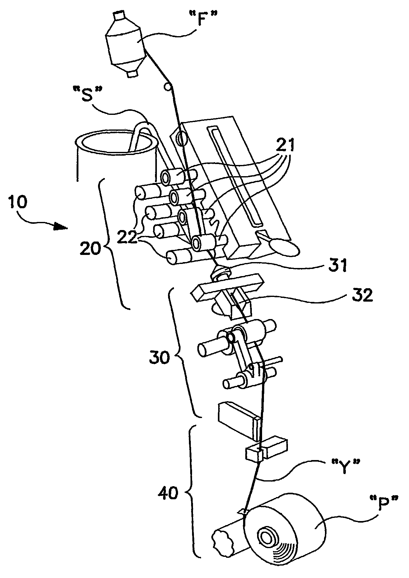
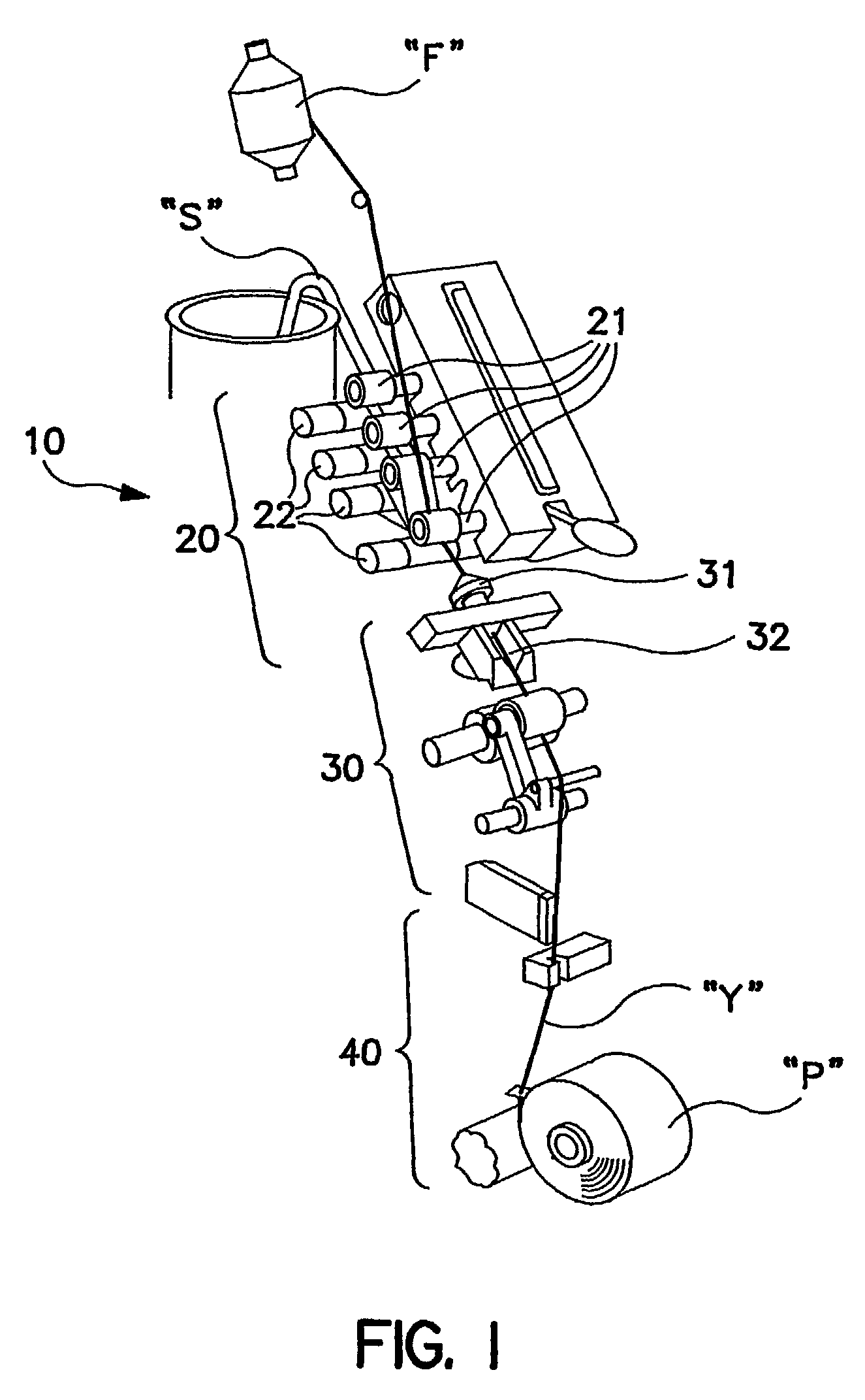
[0038] Referring now specifically to the drawings, a schematic diagram of a Murata MJS Jet Spinner ("MJS") machine which can be configured to produce a yarn according to the present invention is illustrated in FIG. 1 and shown generally at reference numeral 10. Machine 10 includes a drafting zone 20, a spinning zone 30 and a winding zone 40. In conventional jet spinning, a drawn sliver "S" is supplied directly to sets of upper and lower drafting rolls 21, 22, where the sliver is drafted by moving the generally longitudinally-extending fibers past each other in a controlled manner and at controlled rate. The drafted fibers pass through two compressed air nozzles 31, 32 in the spinning zone 30. Compressed air discharged by nozzle 31 whirls about the axis of the nozzle in a direction opposite that discharged by the nozzle 32, thus producing a yarn. The nozzle 32 gathers a group of fibers fed from the drafting rolls 21, 22 by false twisting. Between the front roller in the drafting zone...


PUM


Abstract

A composite matrix yarn (Y) including a cover yarn (80) formed of a plurality of twisted fibers, a core strand (70) positioned within the cover yarn (80) and around which the fibers of the cover yarn (80) are twisted to provide mechanical adhesion between the cover yarn (80) and the core strand (70), and an adhesive binder (75) carried on the core strand (70) for providing enhanced adhesion between the core strand (70) and the cover yarn (80).

Description

[0001] This application is based upon and claims the filing date of provisional patent application No. 60 / 190,674, filed on Mar. 20, 2000.TECHNICAL FIELD AND BACKGROUND OF THE INVENTION[0002] This invention relates to a composite construction made from drafted staple fiber, a suitable chemical and / or transformable fiber, and a filament component or components inserted into the approximate strand center by means of air jet and / or open-end spinning techniques. The filament yarn or yarns form a core upon which a binder formed of chemical compound and / or thermoplastic fiber is applied. A staple cover is spun around the core and binder to form the composite yarn. The present invention relates to producing a commercially viable matrix yarn with unique properties and a process to combine several components of mono- or multifilament core, treatment, and cover construction.[0003] A chemical and / or thermoplastic binder may be applied to the core by means of an emulsion trough or pass-through ...

Claims


Application Information

Patent Timeline
IPC IPC(8): D02G3/36D02G3/40
CPCD02G3/40D02G3/36
Inventor BAKER JR., PAUL W
Owner BAKER JR PAUL W
Learn More