Screen printing method

a screen printing and printing surface technology, applied in the direction of coatings, conductive pattern formation, inking apparatus, etc., can solve the problems of difficult removal of bubbles, uneven surface of printed surface, and inability to encapsulate electronic parts with resin,

Inactive Publication Date: 2003-10-09
NEW LONG SEIMITSU INDS
View PDF5 Cites 15 Cited by
  • Summary
  • Abstract
  • Description
  • Claims
  • Application Information

AI Technical Summary

Problems solved by technology

Also, in the screen printing by a stencil using a stencil made of a metal, bubbles are accumulated at the bottom portion of the pore portions of the stencil, so that resin encapsulation of electronic parts cannot be carried out when the electronic parts are required to have high quality and high performances.
However, in the conventional screen printing method, a thickness of ink in an ink fountain is thick and thus bubbles are difficultly removed.
Also, in the screen printing method using a stencil under vacuum atmosphere, bubbles are removed from the surface of the resin encapsulated portion provided by printing when it is returned to atmospheric pressure from vacuum atmosphere, so that unevenness occurs on the surface of the printed surface by the popped bubbles.
The positions or sizes of the popped bubbles cannot be expected and controlled so that there is a fear of causing significant gaps in an amount or thickness of the paste state or ink state coating material to be printed.
Also, when a stencil is contacted to the printing surface of a material to be printed and printing is carried out such that a paste state or ink state coating material is flown into a pore portion of the stencil, a stencil and a material to be printed are incompletely adhered.
Thus, a coating material is migrated from the pore portion of the stencil to the back surface side thereof so that there is a fear of adhering a coating material to an unintentional portion of the surface of the material to be coated.
Moreover, in a screen printing method using a screen plate comprising a gauze adhered plate, when printing is carried out to a material to be printed by coating a paste state or ink state coating material on the surface of the screen plate by a scraper, and then, a paste fountain or ink fountain stand in one end side of the surface of the screen plate by a squeegee, excessive coating material is printed to the material to be printed by the screen plate.
Thus, there is a fear of attaching the coating material to the portion of the material to be printed other than that desired to be printed or oozing occurs.

Method used


Image

  • Screen printing method
  • Screen printing method
  • Screen printing method

Examples


first embodiment

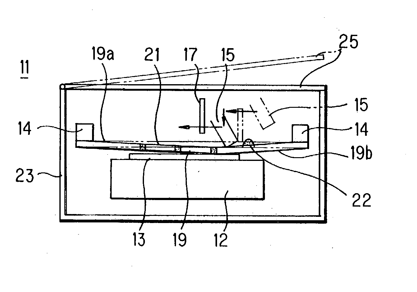
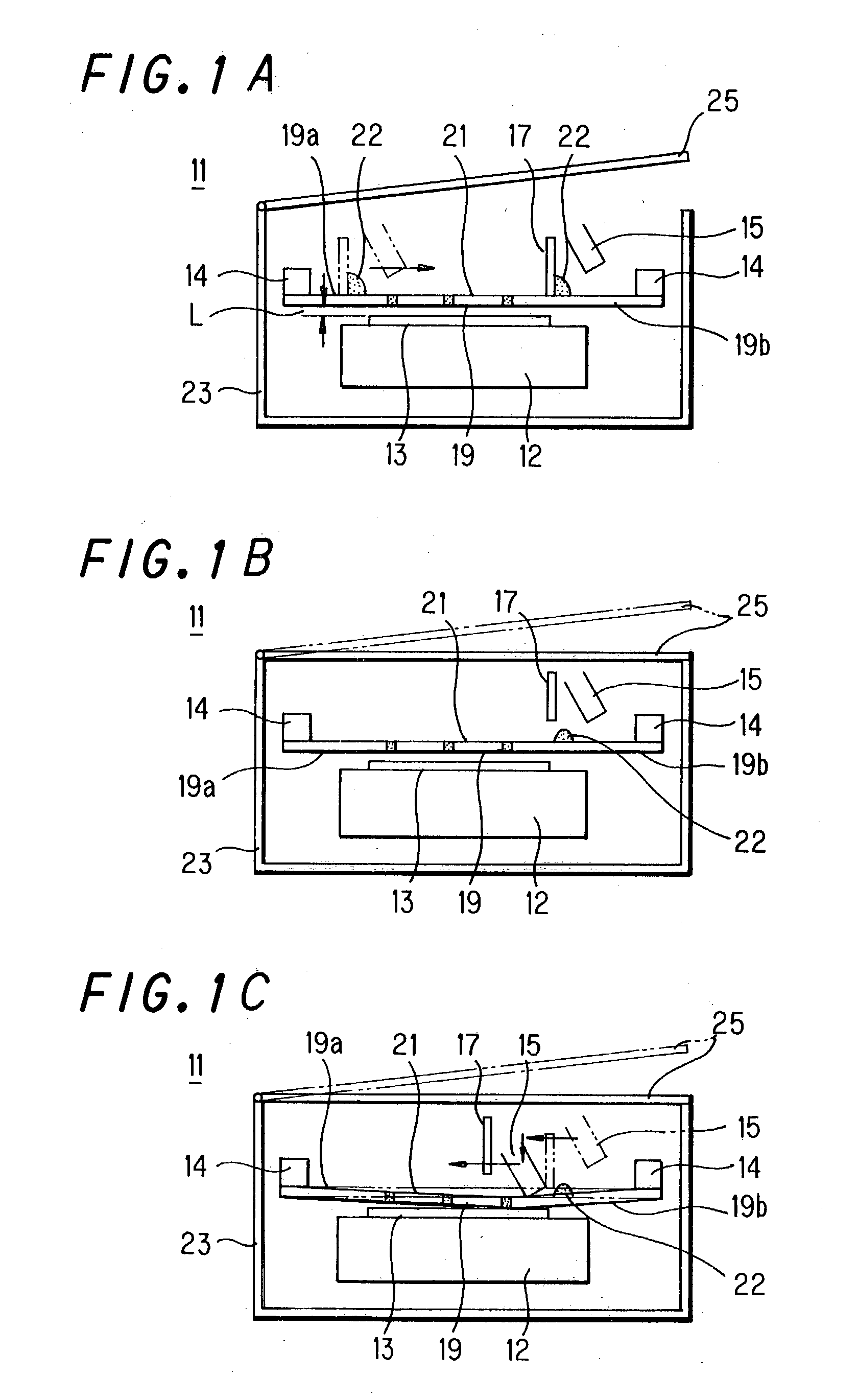
[0044] As explained above, according to the screen printing method of the present invention, it comprises a coating step of covering the paste state or ink state coating material on the surface of the screen plate for printing with a thin thickness, and a printing step in which the paste state or ink state coating material coated on the surface of the screen plate for printing is printed to a material to be printed by the above-mentioned squeegee under vacuum or atmospheric pressure, and after the above-mentioned coating step, a degassing step is provided to degas bubbles in the coated material by changing the pressure from high vacuum state to atmospheric pressure or low vacuum state, so that degassing can be carried out from the paste state or ink state coating material before printing, occurrence of unevenness on the surface of the printing surface due to the effect of bubbles split at the surface of the printed resin encapsulating portion, an amount or a thickness of the paste s...

second embodiment

[0045] Also, according to the screen printing method of the present invention, it comprises a coating step of covering a paste state or ink state coating material on the surface of the screen plate for printing with a thin thickness, and a printing step in which the paste state or ink state coating material coated on the surface of the screen plate for printing got over an ink fountain stood at a side of one edge of the surface of the screen plate in the coating step is printed by the above-mentioned squeegee in vacuum or atmospheric pressure, so that an amount or a thickness of the paste state or ink state coating materials to be printed can be made uniform, screen printing of high quality and high performance can be carried out, attachment of a coating material to an unintentional portion of the surface of a material to be printed by migrating the coating material from a pore portion of the stencil to the back surface side of the stencil can be prevented, and an excessive printing...

third embodiment

[0046] Also, according to the screen printing method of the present invention, it comprises a coating step of covering a paste state or ink state coating material on the surface of the screen plate for printing with a thin thickness, and a printing step in which the paste state or ink state coating material coated on the surface of the screen plate for printing got over an ink fountain stood at a side of one edge of the surface of the screen plate in the coating step is printed by the above-mentioned squeegee in vacuum or atmospheric pressure, and after the above-mentioned coating step, a degassing step is provided to degas bubbles in the coated material by changing the pressure from high vacuum state to atmospheric pressure or low vacuum state, so that degassing can be carried out from the paste state or ink state coating material before printing, occurrence of unevenness on the surface of the printing surface due to the effect of bubbles split at the surface of the printed resin e...


PUM


Abstract

Disclosed are a screen printing method which is carried out by placing a material to be printed at a predetermined portion of a printing table, feeding a paste state or ink state coating material to a surface of a screen plate for printing, and sliding the surface of the screen plate by using a squeegee to carry out screen printing, the method comprises the steps of a coating step in which the above-mentioned paste state or ink state coating material is covering on the surface of the screen plate for printing with a thin thickness, and a printing step in which the paste state or ink state coating material coated on the surface of the screen plate for printing is printed to a material to be printed by the above-mentioned squeegee under vacuum or atmospheric pressure, and after the above-mentioned coating step, a degassing step is provided to degas bubbles in the coated material by changing the pressure from high vacuum state to atmospheric pressure or low vacuum state.

Description

[0001] 1. Field of the Invention[0002] The present invention relates to a screen printing method, more specifically to a screen printing method in which screen printing is carried out by placing a material to be printed on a printing table at a predetermined portion, feeding a coating material in a paste state or an ink state onto the surface of a screen plate for printing and sliding a squeegee on the surface of the screen plate.[0003] 2. Prior Art[0004] In screen printing, a desired printing has been carried out on a printing surface of a material to be printed by placing the material to be printed on a predetermined portion of a printing table, feeding a paste state or ink state coating material comprising an insulating material or a dielectric material onto the surface of a screen plate for printing using a squeegee or a squeegee and a scraper.[0005] The conventional screen printing method has been usually carried out under atmospheric pressure, and there exists a screen printin...

Claims


Application Information

Patent Timeline
Patent Type & Authority Applications(United States)
IPC IPC(8): B41F15/40B41F15/08B41M1/12H05K3/12
CPCB41M1/12H05K2203/085H05K3/1233H05K3/12
Inventor KUDOH, TSUKASA
Owner NEW LONG SEIMITSU INDS
Why Eureka
Try Eureka