
System and method of broad band optical end point detection for film change indication

a broad band, end point technology, applied in the field of endpoint detection, can solve the problems of copper not being able to successfully polish copper, excessive diffusion barrier and metallization material, and affecting the production efficiency of additional metallization layers

Inactive Publication Date: 2003-10-02
APPLIED MATERIALS INC
View PDF11 Cites 62 Cited by
  • Summary
  • Abstract
  • Description
  • Claims
  • Application Information

AI Technical Summary

Problems solved by technology

Without planarization, fabrication of additional metallization layers becomes substantially more difficult due to the higher variations in the surface topography.
Some excessive diffusion barrier and metallization material is also inevitably deposited over the field areas.
Endpoint detection for copper is performed because copper cannot be successfully polished using a timed method.
A timed polish does not work with copper because the removal rate from a CMP process is not stable enough for a timed polish of a copper layer.
However, none of the methods except for the friction sensing have achieved some commercial success in the industry.
Unfortunately, this method is not robust to process changes.
Further, the endpoint detected is global, and thus the method cannot detect a local endpoint at a specific point on the wafer surface.
Moreover, the method of the U.S Pat. No. 6,186,865 patent is restricted to a linear polisher, which requires an air bearing.
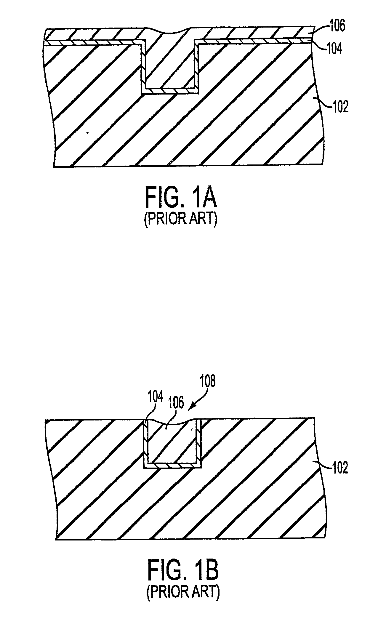
A common problem with current endpoint detection techniques is that some degree of over-polishing is required to ensure that all of the conductive material (e.g., metallization material or diffusion barrier layer 104) is removed from over the dielectric layer 102 to prevent inadvertent electrical interconnection between metallization lines.
Dishing is known to impact the performance of the interconnect metallization lines in a negative way, and too much dishing can cause a desired integrated circuit to fail for its intended purpose.
Prior art methods typically can only approximately predict the actual end point but cannot actually detect the actual end point.

Method used


Image

  • System and method of broad band optical end point detection for film change indication
  • System and method of broad band optical end point detection for film change indication
  • System and method of broad band optical end point detection for film change indication

Examples


Embodiment Construction

[0046] Several exemplary embodiments for optically determining an endpoint will now be described. It will be apparent to those skilled in the art that the present invention may be practiced without some or all of the specific details set forth herein.

[0047] An important control aspect of the chemical mechanical polishing (CMP) system is determining when the process is at an end, i.e., when to stop the CMP process. Prior art systems described above, typically predict and endpoint based on various detected data points but cannot accurately detect an exact endpoint as will be described in more detail below.

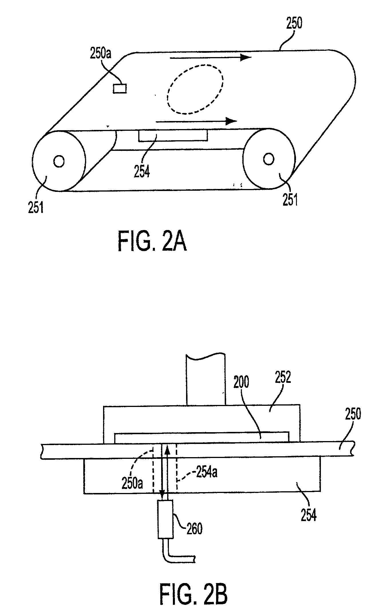
[0048] FIG. 2A shows a CMP system in which a pad 250 is designed to rotate around rollers 251, in accordance with an embodiment of the present invention. A platen 254 is positioned under the pad 250 to provide a surface onto which a wafer will be applied using a carrier 252. Endpoint detection is performed using an optical detector 260 in which light is applied through the platen 254...


PUM


Abstract

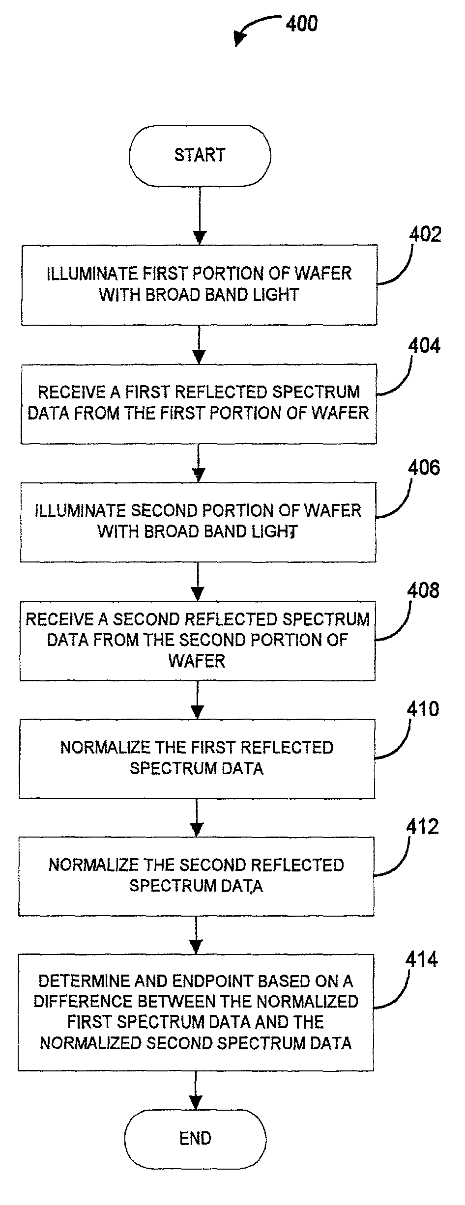
A system and method for detecting an endpoint during a chemical mechanical polishing process is disclosed that includes illuminating a first portion of a surface of a wafer with a first broad beam of light. A first reflected spectrum data is received. The first reflected spectrum of data corresponds to a first spectra of light reflected from the first illuminated portion of the surface of the wafer. A second portion of the surface of the wafer with a second broad beam of light. A second reflected spectrum data is received. The second reflected spectrum of data corresponds to a second spectra of light reflected from the second illuminated portion of the surface of the wafer. The first reflected spectrum data is normalized and the second reflected spectrum data is normalized. An endpoint is determined based on a difference between the normalized first spectrum data and the normalized second spectrum data.

Description

[0001] 1. Field of the Invention[0002] This invention relates generally to endpoint detection in a chemical mechanical polishing process, and more particularly to endpoint detection using optical interference of a broad reflectance spectrum.[0003] 2. Description of the Related Art[0004] In the fabrication of semiconductor devises, typically, the integrated circuit devices are in the form of multi-level structures. At the substrate level, transistor devices having diffusion regions are formed. In subsequent levels, interconnect metallization lines are patterned and electrically connected to the transistor devices to define the desired functional device. As is well known, patterned conductive layers are insulated from other conductive layers by dielectric materials, such as silicon dioxide. As more metallization levels and associated dielectric layers are formed, the need to planarize the dielectric material increases. Without planarization, fabrication of additional metallization lay...

Claims


Application Information

Patent Timeline
IPC IPC(8): B24B37/013B24B49/12G01B11/06G01J3/00G01N21/27H01L21/304H01L21/66
CPCB24B37/013B24B49/12G01J3/00G01B11/0683G01B11/0625H01L21/304H01L22/00H01L21/306
Inventor KATZ, VLADIMIRMITCHELL, BELLA
Owner APPLIED MATERIALS INC
Learn More