
Organic carbonate additives for nonaqueous electrolyte rechargeable electrochemical cells

a rechargeable electrochemical cell and organic carbonate technology, applied in the field of alkali metal electrochemical cells, can solve the problems of limited choice of electrolyte solvent systems, permanent capacity loss, and general cathode limitation of lithium ion cells

Inactive Publication Date: 2003-07-10
WILSON GREATBATCH LTD
View PDF0 Cites 33 Cited by
  • Summary
  • Abstract
  • Description
  • Claims
  • Application Information

AI Technical Summary

Benefits of technology

[0003] Alkali metal rechargeable cells typically comprise a carbonaceous anode electrode and a lithiated cathode electrode. Due to the high potential of the cathode material (up to 4.3V vs. Li / Li+for Li.sub.1-xCoO.sub.2) and the low potential of the carbonaceous anode material (0.01V vs. Li / Li+for graphite) in a fully charged lithium ion cell, the choice of the electrolyte solvent system is limited. Since carbonate solvents have high oxidative stability toward typically used lithiated cathode materials and good kinetic stability toward carbonaceous anode materials, they are generally used in lithium ion cell electrolytes. To achieve optimum cell performance (high rate capability and long cycle life), solvent systems containing a mixture of a cyclic carbonate (high dielectric constant solvent) and a linear carbonate (low viscosity solvent) are typically used in commercial secondary cells. Cells with carbonate-based electrolytes are known to deliver more than 1,000 charge / discharge cycles at room temperature.
[0005] According to the present invention, these objectives are achieved by providing an organic carbonate in the quaternary solvent electrolyte. Lithium ion cells activated with these electrolytes exhibit lower first cycle irreversible capacities relative to cells activated with the same quaternary solvent electrolyte devoid of the carbonate additive. As a result, cells including the carbonate additive presented higher subsequent cycling capacity than the control cells. The cycleability of the present invention cells at room temperature, as well as at low temperatures, i.e., down to about -20.degree. C., is as good as cells activated with the quaternary electrolyte devoid of a carbonate additive.
[0008] Hence, the composition of the electrolyte has a significant influence on the discharge efficiency of alkali metal systems, and particularly the permanent capacity loss in secondary cells. For example, when 1.0M LiPF.sub.6 / EC:DMC =30:70 is used to activate a secondary cell, the first cycle irreversible capacity is approximately 35 mAh / g of graphite. However, under the same cycling conditions, the first cycle irreversible capacity is found to be approximately 65 mAh / g of graphite when 1.0M LiPF.sub.6 / EC:DMC:EMC:DEC =45:22:24.8:8.2 is used as the electrolyte. In contrast, lithium ion cells activated with the binary solvent electrolyte of ethylene carbonate and dimethyl carbonate cannot be cycled at temperatures less than about -11.degree. C. The quaternary solvent electrolyte of EC, DMC, EMC and DEC, which enables lithium ion cells to cycle at much lower temperatures, is a compromise in terms of providing a wider temperature application with acceptable cycling efficiencies. It would be highly desirable to retain the benefits of a lithium ion cell capable of operating at temperatures down to as low as about 31 40.degree. C. while minimizing the first cycle irreversible capacity.
[0009] According to the present invention, these objectives are achieved by adding a carbonate additive in the above-described quaternary solvent electrolytes. In addition, this invention may be generalized to other nonaqueous organic electrolyte systems, such as binary solvent and ternary solvent systems, as well as the electrolyte systems containing solvents other than mixtures of linear or cyclic carbonates. For example, linear or cyclic ethers or esters may also be included as electrolyte components. Although the exact reason for the observed improvement is not clear, it is hypothesized that the carbonate additive competes with the existing electrolyte components to react on the carbon anode surface during initial lithiation to form a beneficial SET film. The thusly-formed SET film is electrically more insulating than the film formed without the carbonate additive and, as a consequence, the lithiated carbon electrode is better protected from reactions with other electrolyte components. Therefore, lower first cycle irreversible capacity is obtained.

Problems solved by technology

Li / Li+for graphite) in a fully charged lithium ion cell, the choice of the electrolyte solvent system is limited.
However, lithium ion cell design generally involves a trade off in one area for a necessary improvement in another, depending on the targeted cell application.
Due to the existence of this first cycle irreversible capacity, lithium ion cells are generally cathode limited.
It is commonly known that when an electrical potential is initially applied to lithium ion cells constructed with a carbon anode in a discharged condition to charge the cell, some permanent capacity loss occurs due to the anode surface passivation film formation.
The formation of a surface film is unavoidable for alkali metal systems, and in particular, lithium metal anodes, and lithium intercalated carbon anodes due to the relatively low potential and high reactivity of lithium toward organic electrolytes.
While most alkali metal, and in particular, lithium electrochemical systems meet the first requirement, the second requirement is difficult to achieve.
The resistance of these films is not negligible, and as a result, impedance builds up inside the cell due to this surface layer formation, which induces unacceptable polarization during the charge and discharge of the lithium ion cell.
However, this approach is compromised by problems associated with handling lithiated carbon outside of the cell.
The choice of an electrolyte solvent system for activating an alkali metal electrochemical cell, and particularly a fully charged lithium ion cell is very limited due to the high potential of the cathode material (up to 4.3V vs.
Such unpredictability is not acceptable in a lithium ion cell.

Method used


Image

  • Organic carbonate additives for nonaqueous electrolyte rechargeable electrochemical cells
  • Organic carbonate additives for nonaqueous electrolyte rechargeable electrochemical cells
  • Organic carbonate additives for nonaqueous electrolyte rechargeable electrochemical cells

Examples


example ii

[0044] After the initial cycle, the cycling of the twelve cells continued for a total of 10 times under the same cycling conditions as described in Example I. The discharge capacities and the capacity retention of each cycle are summarized in Table 3. The capacity retention is defined as the capacity percentage of each discharge cycle relative to that of the first cycle discharge capacity.

3TABLE 3 Cycling Discharge Capacity and Capacity Retention Group 1 Group 2 Reten- Reten- Group 3 Cycle Capacity tion Capacity tion Capacity Retention # (mAh) (%) (mAh) (%) (mAh) (%) 1 516.0 100.0 550.1 100.0 548.7 100.0 2 508.4 98.5 542.5 98.6 540.0 98.4 3 503.5 97.6 537.0 97.6 533.5 97.2 4 498.4 96.6 531.8 96.7 528.0 96.2 5 494.6 95.9 527.7 95.9 523.7 95.4 6 491.4 95.2 524.1 95.3 519.9 94.8 7 488.7 94.7 521.5 94.8 517.1 94.2 8 486.7 94.3 518.5 94.2 513.9 93.7 9 484.0 93.8 516.4 93.9 511.9 93.3 10 483.3 93.7 514.3 93.5 509.7 92.9

[0045] The data in Table 3 demonstrate that the group 2 and 3 cells wi...

example iii

[0046] After the above cycle testing described in Example II, the cells were charged according to the procedures described in Example I. Then, the cells were discharged under a 1000 mA constant current to 2.75 V then a five minute open circuit rest, followed by a 500 mA constant current discharge to 2.75 V then a five minute open circuit rest, followed by a 250 mA constant current discharge to 2.75 V then a five minute open circuit rest and, finally, followed by a 100 mA constant current discharge to 2.75 V then a five minute open circuit rest. The averaged total capacities under each discharge rate are summarized in Table 4 and the comparison of averaged discharge efficiency (defined as % capacity of a 100 mA constant current discharge) under the various constant currents is summarized in Table 5. In Table 4, the discharge capacities are cumulative from one discharge current to the next.

4TABLE 4 Discharge Capacities (mAh) under Various Currents Group 1000 mA 500 mA 250 mA 100 mA 1 ...

example iv

[0049] After the above discharge rate capability test, all the cells were fully charged according to the procedure described in Example I. The twelve test cells were then stored on open circuit voltage (OCV) at 37.degree. C. for two weeks. Finally, the cells were discharged and cycled eight more times. The % of self-discharge and the capacity retention were calculated and are shown in Table 6.

6TABLE 6 Rates of Self-Discharge and After Storage Capacity Retention Group Self-Discharge (%) Capacity Retention (%) 1 13.6 92.3 2 15.4 93.5 3 13.9 92.9

[0050] The data in Table 6 demonstrate that all three groups of cells exhibited similar self-discharge rates and similar after storage capacity retention rates. However, since the group 2 and 3 cells had higher discharge capacities than that of the group 1 cells, the capacities of the group 2 and 3 cells were still higher than that of the group 1 cells, even though they presented similar self-discharge and capacity retention rates. A total of 2...


PUM

PropertyMeasurementUnit
dissociation energyaaaaaaaaaa
temperature cycleabilityaaaaaaaaaa
temperaturesaaaaaaaaaa

Abstract

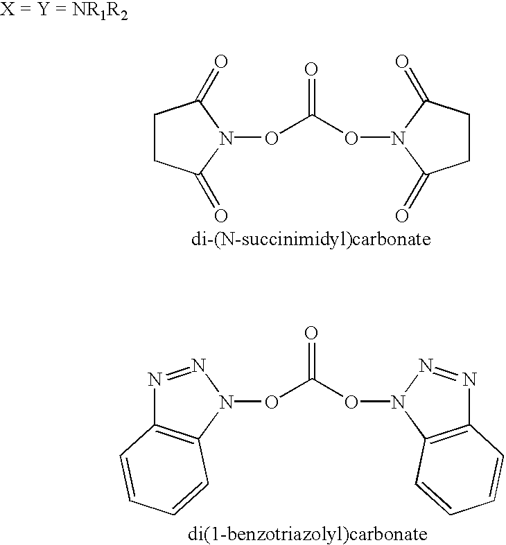
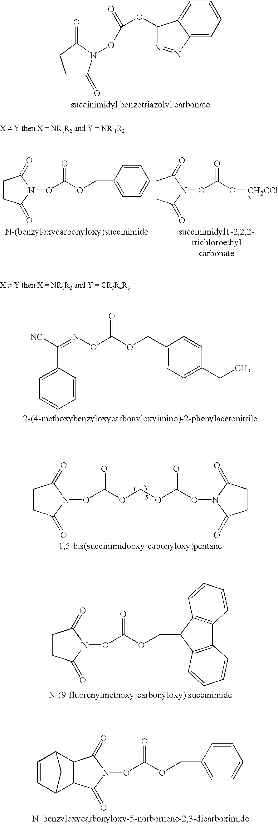
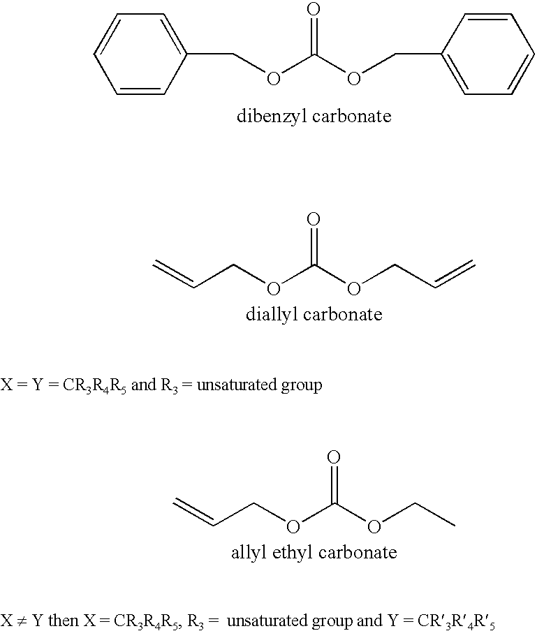
A lithium ion electrochemical cell having high charge / discharge capacity, long cycle life and exhibiting a reduced first cycle irreversible capacity, is described. The stated benefits are realized by the addition of at least one carbonate additive to an electrolyte comprising an alkali metal salt dissolved in a solvent mixture including ethylene carbonate, dimethyl carbonate, ethyl methyl carbonate and diethyl carbonate. The preferred additive is either a linear or cyclic carbonate containing covalent O-X and O-Y bonds on opposite sides of a carbonyl group wherein at least one of the O-X and the O-Y bonds has a dissociation energy less than about 80 kcal / mole.

Description

[0001] The present application is a continuation-in-part of application Ser. No. 09 / 738,143, abandoned, which is a continuation-in-part of application Ser. No. 09 / 302,773, abandoned, which claims priority based on U.S. provisional application Ser. No. 60 / 105,280, filed Oct. 22, 1998.BACKGROUND OF INVENTION[0002] The present invention generally relates to an alkali metal electrochemical cell, and more particularly, to a rechargeable alkali metal cell. Still more particularly, the present invention relates to a lithium ion electrochemical cell activated with an electrolyte having an additive provided to achieve high charge / discharge capacity, long cycle life and to minimize the first cycle irreversible capacity. According to the present invention, the preferred additive to the activating electrolyte is a carbonate compound.[0003] Alkali metal rechargeable cells typically comprise a carbonaceous anode electrode and a lithiated cathode electrode. Due to the high potential of the cathode...

Claims


Application Information

Patent Timeline
Patent Type & Authority Applications(United States)
IPC IPC(8): H01M4/58H01M4/587H01M6/16H01M10/0525H01M10/0567H01M10/0568H01M10/0569H01M10/36
CPCH01M4/587H01M6/168H01M10/0525H01M10/0567Y10T29/49108H01M10/0569H01M2300/0037Y02E60/122H01M10/0568Y02E60/10
Inventor GAN, HONGTAKEUCHI, ESTHER S.RUBINO, ROBERT
Owner WILSON GREATBATCH LTD
Learn More