
Adaptive array device, wireless base station and cellular telephone

a technology of adaptive array and wireless base station, which is applied in the direction of electromagnetic wave modulation, differential interacting antenna combinations, and receiving monitoring, etc., can solve the problems of increasing the inability of the mobile phone to perform the function of controlling the directivity pattern, and the scale of the circuit. , to achieve the effect of reducing the overall scale of the circui

Inactive Publication Date: 2003-05-22
HERA WIRELESS
View PDF17 Cites 16 Cited by
  • Summary
  • Abstract
  • Description
  • Claims
  • Application Information

AI Technical Summary

Benefits of technology

[0016] Additionally, the adaptive array apparatus may be arranged so that a gain of the antenna of a second radio unit is less than a gain of the antenna of the first radio unit, the retaining means further retains a compensation value that compensates for the gain of the antenna of the second radio unit, and the amplitude correction unit corrects the amplitude of the signal to be transmitted from the second radio unit using the compensation value.
[0019] With this arrangement, since the correction means uses the correction weight coefficient to control weighting performed by the weighting means, it is possible to use the weighting means that is naturally provided within the adaptive array apparatus. This does away with the requirement for separate correction circuitry within the apparatus, which results in the reduction of the overall scale of circuitry.

Problems solved by technology

When an adaptive array is used in a mobile phone system, the mobile phone unit has physical limitations such as size and possible number of antennas, making it impossible for the mobile phone to perform the function of controlling the directivity pattern.
However, even if the weight vector calculated at the time of reception is used at the time of transmission, it is not always the case that the same array antenna pattern will be formed for transmission and reception.
This additional equipment is required within the adaptive array apparatus of the prior art to assess the difference between transfer characteristics of transmission circuits and reception circuits in each separate radio unit, causing a problem wherein the scale of the circuits are increased.
In other words, the problem with the prior art is that the scales of its circuits are increased in order to include a calibration-specific circuit that would not be required in regular communication.

Method used


Image

  • Adaptive array device, wireless base station and cellular telephone
  • Adaptive array device, wireless base station and cellular telephone
  • Adaptive array device, wireless base station and cellular telephone

Examples


Embodiment Construction

[0035] The preferred embodiment of the radio base station, mobile phone, and measurement apparatus of the present invention will be explained in the following order.

[0036] 1. Radio Base Station

[0037] 1.1. Overview

[0038] 1.1.1. General Structure

[0039] 1.1.2. General Operations

[0040] 1.1.3. Supplementary Explanation

[0041] 1.2. Structure of Radio Base Station

[0042] 1.2.1. Structure of Digital Signal Processor

[0043] 1.2.2. Structure of User Signal Processing Unit

[0044] 1.2.3. Calibration Process

[0045] 2. Mobile Phone

[0046] 2.1. Structure

[0047] 3. Measurement Apparatus

[0048] 3.1. Structure

[0049] 3.2. Calibration Process

[0050] 4. Examples of Other Variations of the Invention

[0051] 1. Radio Base Station

[0052] 1.1. Overview

[0053] The following is a general overview of an adaptive array apparatus of the preferred embodiment when it performs the function of a radio base station in a mobile communications network.

[0054] 1.1.1. General Structure

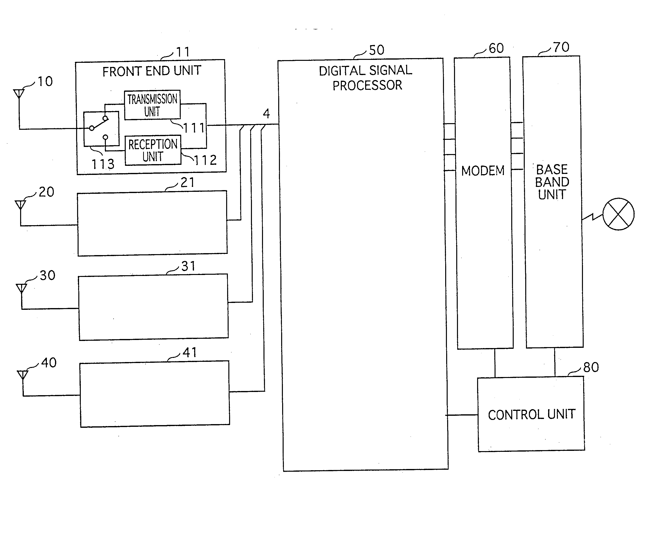
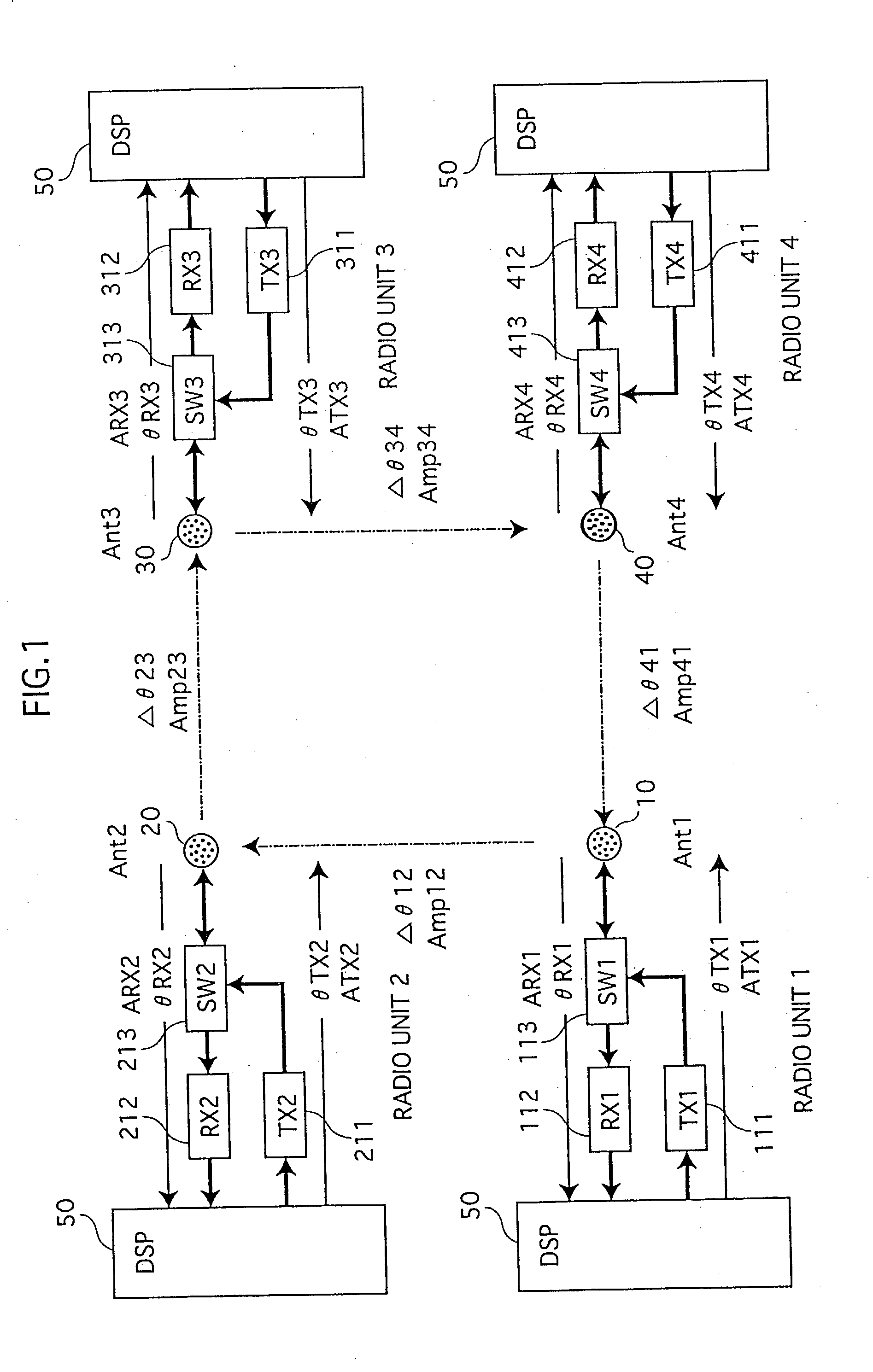
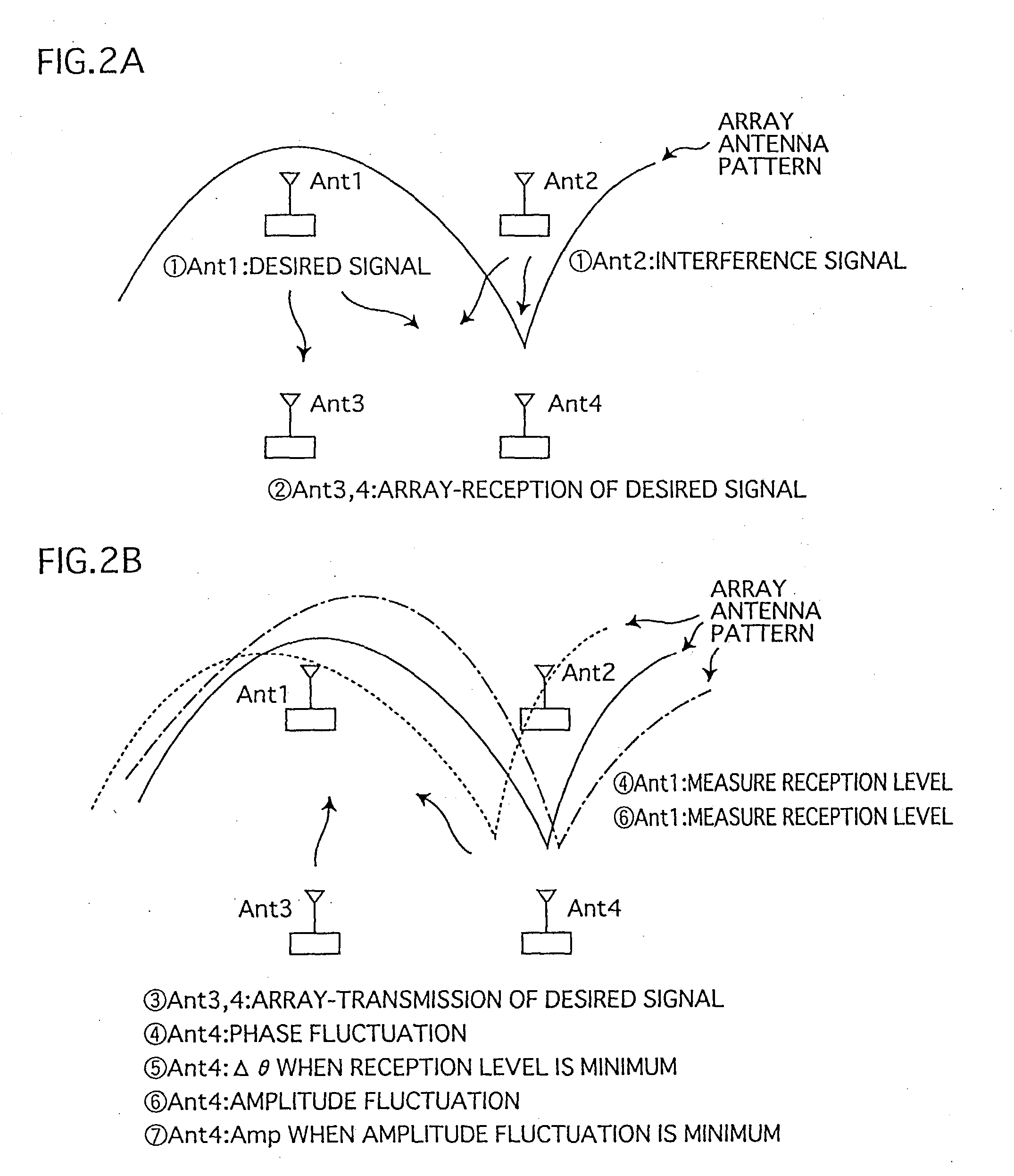
[0055] FIG. 1 shows the general structure of the p...


PUM


Abstract

Memory (237) stores relative correction values that indicate the differences of transfer characteristics between a) a radio unit made up of transmission circuit (211) and reception circuit (212), and b) a radio unit made up of transmission circuit (221) and reception circuit (222). Correction control unit (239), by means of phase shifter (240) and amplifier (241), uses the relative correction values to correct transmission signals. In similar fashion, the adaptive array apparatus and the radio base station perform corrections in order that identical array antenna patterns are formed at times of reception and transmission.

Description

TECHNICAL FIELD[0001] The present invention relates to an adaptive array apparatus, a radio base station, and a mobile phone for correcting the differences of the transfer characteristics between a transmission unit and a reception unit of a plurality of radio systems within an adaptive array apparatus designed for wireless communication.BACKGROUND ART[0002] With the recent increase in mobile stations such as PHS devices and mobile phones, there is an increasing social need for more effective use of radio wave frequency resources. An example of a communication method that addresses this need is the spatial multiplexing method.[0003] The spatial multiplexing method is a communication method that involves the usage of an adaptive array apparatus that forms a different directivity pattern (called an adaptive array pattern) for each of a plurality of mobile stations. By doing this, the adaptive array apparatus is able to perform communication functions by multiplexing the transmission a...

Claims


Application Information

Patent Timeline
Patent Type & Authority Applications(United States)
IPC IPC(8): H01Q3/26H01Q21/29H04B1/3822H04B1/40H04B7/06H04B7/08H04B7/10H04W16/28H04W88/02
CPCH01Q3/2605H01Q21/29H04B7/0615H04B7/0848H04B17/12H04B17/20H04B7/2603H04B7/2612
Inventor DOI, YOSHIHARUNAKAO, SEIGOMAKITA, TAKAAI
Owner HERA WIRELESS
Learn More