
Coaxial connector and manufacture thereof

a technology of coaxial connectors and connectors, applied in the direction of coupling device connections, coupling device details, two-pole connections, etc., can solve the problems of inability unable to effectively shield electromagnetic waves, and section of a conventional bnc connector having a certain thickness inevitably fails to prevent electromagnetic waves

Inactive Publication Date: 2003-05-15
JST MFG CO LTD
View PDF5 Cites 18 Cited by
  • Summary
  • Abstract
  • Description
  • Claims
  • Application Information

AI Technical Summary

Benefits of technology

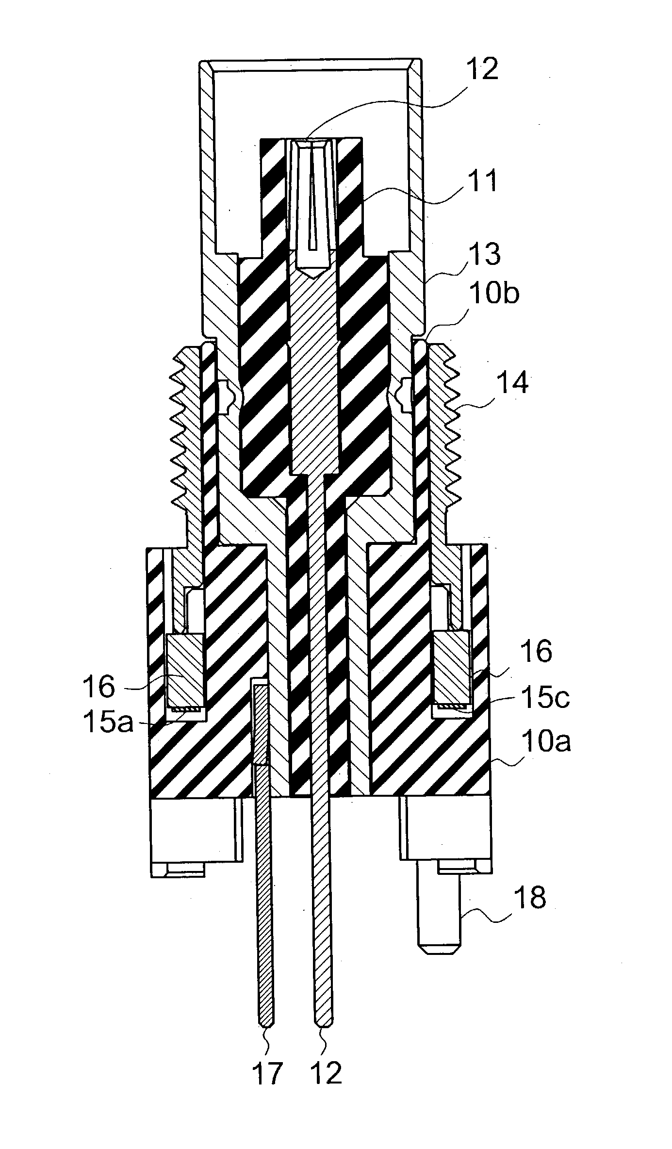
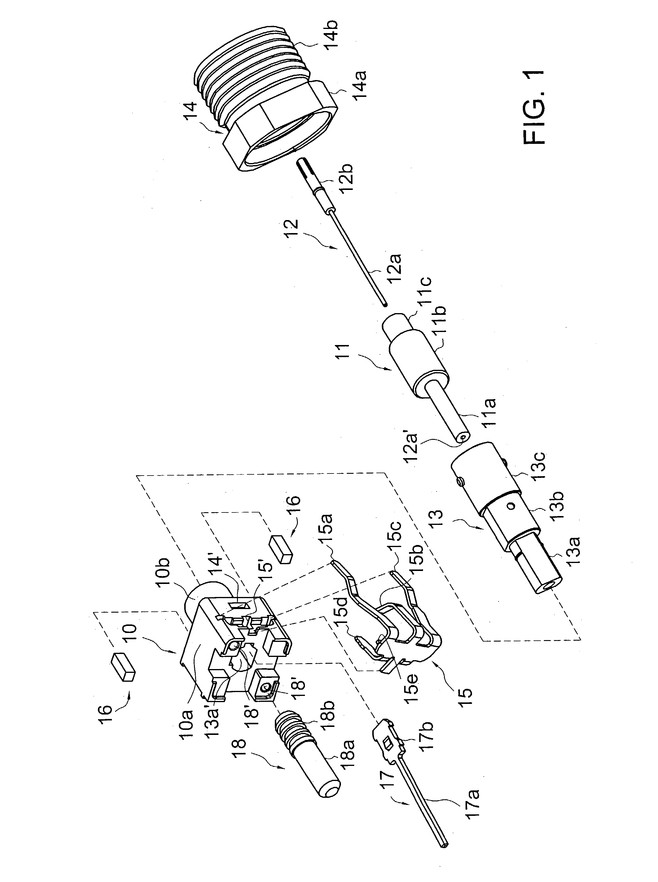
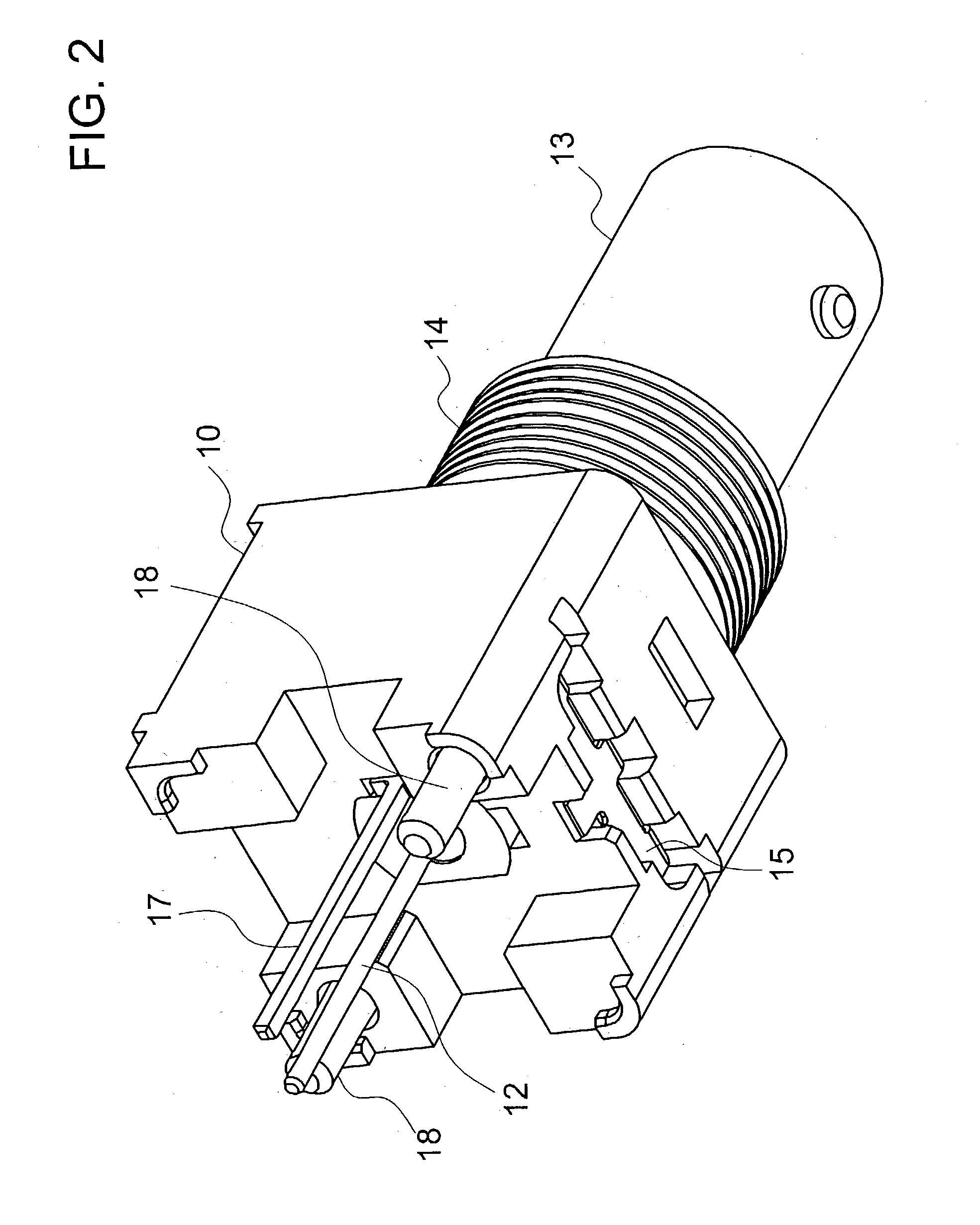
[0029] According to the present invention, a conductive member for shielding (or blocking) passage of an electromagnetic wave is provided on an outer periphery of a cylindrical part of an insulation main body of a coaxial connector. And a connection portion of the coaxial connector has a structure having an external conductor, the cylindrical part (a dielectric member), and a conductive member connected in the order so that an electromagnetic wave (noise) that passes the dielectric member may be attenuated between shielding walls of the external conductor and the conductive member, thereby minimizing the leakage of a developed electromagnetic wave from the coaxial connector.
[0071] According to the present invention, the cylindrical part of the insulation main body is made thinner so that the distance between the shield walls constituted of the external conductor and the conductive member becomes small. Hence, in most part between the shield walls, an electromagnetic wave travels uniformly and perpendicular to the walls, thereby enhancing the attenuation efficiency of the electromagnetic wave. Therefore, leakage of the electromagnetic wave from the coaxial connector can be suppressed further.

Problems solved by technology

However, as the thickness of the plastic member (dielectric substance) increases, the distance between shield walls constituted of the external conductor and a conductive panel becomes greater, thereby failing to effectively shield an electromagnetic wave.
Hence, a screw section of a conventional BNC connector having a certain thickness inevitably fails to prevent electromagnetic waves developed in a device from radiating to the outside of the device through the plastic member.
Since the electromagnetic wave with a higher frequency can more easily pass through a dielectric substance due to the properties thereof, a leakage of the electromagnetic waves may become more.
However, the plastic screw may not have enough strength as a mounting portion.
The thickness can be increased for the strength, but a thicker plastic mounting portion may cause leakage of an electromagnetic wave through the portion.
If the electrical contact is provided outside the connector and has a spring finger which can elastically deform to engage with an electric element inserted into the connector, the connection between the electric element and the spring finger by pressing each other may have higher possibility to cause inadequate contact.

Method used


Image

  • Coaxial connector and manufacture thereof
  • Coaxial connector and manufacture thereof
  • Coaxial connector and manufacture thereof

Examples


example

[0122] An electric field intensity profile of the coaxial connector of the embodiment was measured in comparison to the conventional connector.

[0123] The measurement was conducted with a cubic having each edge length of 50 cm. The coaxial connector was mounted on the top face of the cubic, inside of which an electromagnetic wave of 1 GHz is generated.

[0124] With the conventional connector, the range of the electromagnetic wave of high intensity was around the connector. With the connector of the embodiment, the range of the electromagnetic wave of high intensity was much smaller than that with the conventional connector.

[0125] Therefore, use of the coaxial connector according to the present invention effectively lowers radiation of the electromagnetic wave to the outside of the device, thereby contributing to the improvement in electromagnetic compatibility (EMC) and radiation emission.

[0126] As described above, the invention adopts a structure in which a connection portion formed b...


PUM


Abstract

To provide a coaxial connector which inhibits radiation of an electromagnetic wave to the outside of the device and enables improvements in electromagnetic compatibility (EMC); a method of manufacturing the connector; and a method of inhibiting leakage of an electromagnetic wave using the coaxial connector. A connection section to be connected to a conductive panel is formed from a conductive material. A dielectric substance formed for ensuring insulation of an external conductor from a conductive panel is made thin. A dielectric substance (insulator) acting as a radiation rout of an electromagnetic waveform is sandwiched between two conductors.

Description

[0001] 1. Field of the Invention[0002] The invention relates to a coaxial connector connected to a conductive panel, and more particularly, to a coaxial connector, a connecting part of which is to be connected to the conductive panel which is constituted of conductive material.[0003] 2. Related Art[0004] A BNC connector is usually connected as a coaxial connector to be connected to a conductive panel.[0005] In some BNC connectors, a signal ground of an external conductor is coupled directly to a ground frame of the conductive panel, to thereby ensure grounding. When a plurality of devices are interconnected by means of BNC connectors, such a grounding method enables formation of a ground loop by means of a potential difference among the devices. As a result, flow of an electric current arises among the devices.[0006] In order to prevent formation of such a ground loop, there is described a capacitive-coupling connector, as disclosed in Japanese Patent No. 2578675.[0007] In the capac...

Claims


Application Information

Patent Timeline
Patent Type & Authority Applications(United States)
IPC IPC(8): H01R13/719H01R24/44H01R24/52H01R103/00
CPCH01R13/719H01R2103/00H01R24/52H01R24/44H01R24/42
Inventor OTSU, AKIHIKO
Owner JST MFG CO LTD
Learn More