
Grinding tool for grinding buttons of a rock drill bit, a grinding spindle and method for mounting the grinding cup on a grinding spindle

a drilling bit and button technology, which is applied in the direction of grinding machines, boring/drilling apparatus, grinding teeth, etc., can solve the problems of abrasive grinding surface of wear parts of such grinding cups, complicating the design of grinding tools, etc., and achieves the effect of quickly mounting or dismantling

Inactive Publication Date: 2003-03-20
BERGQUIST ARNE +1
View PDF10 Cites 6 Cited by
  • Summary
  • Abstract
  • Description
  • Claims
  • Application Information

AI Technical Summary

Benefits of technology

[0007] Another object of the present invention is to provide a grinding tool that can be mounted or dismantled quickly.

Problems solved by technology

The wear part of such grinding cup usually has an abrasive grinding surface that often comprises diamond particles.
This complicates the design of the grinding tool and requires two hands for demounting of the grinding cup.

Method used


Image

  • Grinding tool for grinding buttons of a rock drill bit, a grinding spindle and method for mounting the grinding cup on a grinding spindle
  • Grinding tool for grinding buttons of a rock drill bit, a grinding spindle and method for mounting the grinding cup on a grinding spindle
  • Grinding tool for grinding buttons of a rock drill bit, a grinding spindle and method for mounting the grinding cup on a grinding spindle

Examples


Embodiment Construction

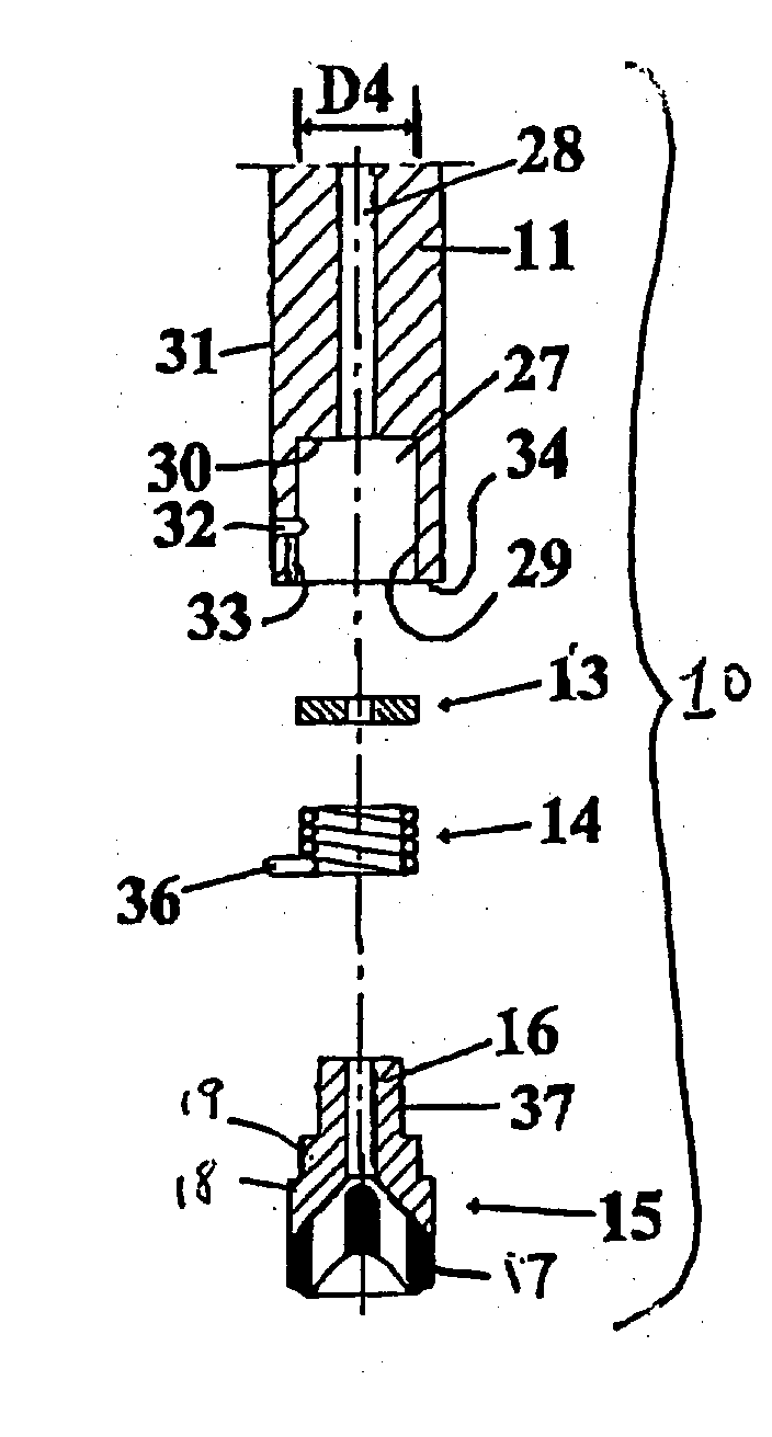
[0032] A first embodiment of a grinding tool 10 according to the present invention for grinding buttons of a rock drill bit is described hereinafter with reference to FIGS. 1A-1J. The tool comprises a grinding spindle 11, a vibration-damping means 13, a mounting means or a spring 14 and a grinding cup 15. In FIG. 1C the tool 10 is shown as mounted to a swivel or flushing head 12 to form a grinding assembly.

[0033] The upper end of the grinding spindle 11 is intended to be rotatably mounted in a grinding head, not shown, of the type shown and described in EP-B-734,306, which hereby is incorporated by reference into the description. The grinding head is thus connected to a power source such as an electric motor and can be vertically displaced, i.e. downwardly and upwardly. The grinding head comprises an external housing (not shown) which is stationary. The grinding spindle 11 is rotatably journalled in a boring of the spindle house by means of roller bearings that are spaced apart axia...


PUM

PropertyMeasurementUnit
diameteraaaaaaaaaa
diameteraaaaaaaaaa
diameteraaaaaaaaaa

Abstract

A grinding tool for grinding buttons of a rock drill bit includes a spindle having a longitudinal axis of rotation, and a grinding cup mounted on the spindle by a tongue-and-socket connection. A fastener in the form of a coil spring secures the grinding cup to the spindle. The grinding cup can be inserted into the inside of, or around the exterior of, the coil spring. When the spindle is rotated in a working direction, the spring tightens against the grinding cup. To install or remove the grinding cup, the grinding cup is rotated relative to the spindle in a direction corresponding to the working direction, whereby engagement between the grinding cup and the coil spring becomes loosened.

Description

[0001] The present invention relates to a grinding tool for grinding buttons of a rock drill bit, a grinding cup, a grinding spindle and a method for mounting the grinding cup on a grinding spindle.PRIOR ART[0002] A conventional grinding tool includes a grinding cup fastened to a rotary spindle, there being a vibration damping device between the spindle and grinding cup.[0003] When grinding cemented carbide buttons of a drill bit, a grinding cup is normally used. The wear part of such grinding cup usually has an abrasive grinding surface that often comprises diamond particles. Grinding of cemented carbide buttons generates both heat and abrasive cuttings to such an extent that it is necessary to cool the grinding cup and the button bit as well as to flush away the cuttings. A prior art means for cooling involves supplying cooling medium, normally water, through the grinding machine and axially through the grinding cup to discharge the cooling medium in the region where the wear part...

Claims


Application Information

Patent Timeline
Patent Type & Authority Applications(United States)
IPC IPC(8): B24B3/33B24B45/00B24D7/10
CPCB24B3/33B24D7/10B24B45/00
Inventor BERGQUIST, ARNELINDGREN, GORAN
Owner BERGQUIST ARNE
Learn More