
Battery pack having perforated terminal arrangement

a terminal arrangement and battery pack technology, applied in secondary cell servicing/maintenance, coupling device connection, instruments, etc., can solve the problems of heavy and expensive packages, and the difficulty of electrically connecting packages in a compact configuration

Inactive Publication Date: 2003-02-20
ENERDEL
View PDF9 Cites 15 Cited by
  • Summary
  • Abstract
  • Description
  • Claims
  • Application Information

AI Technical Summary

Benefits of technology

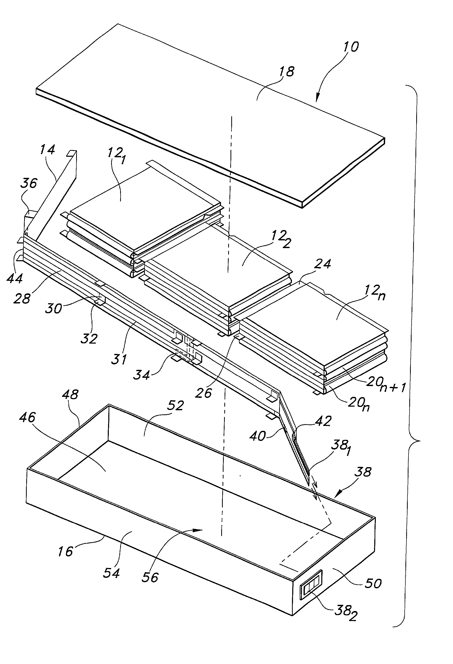
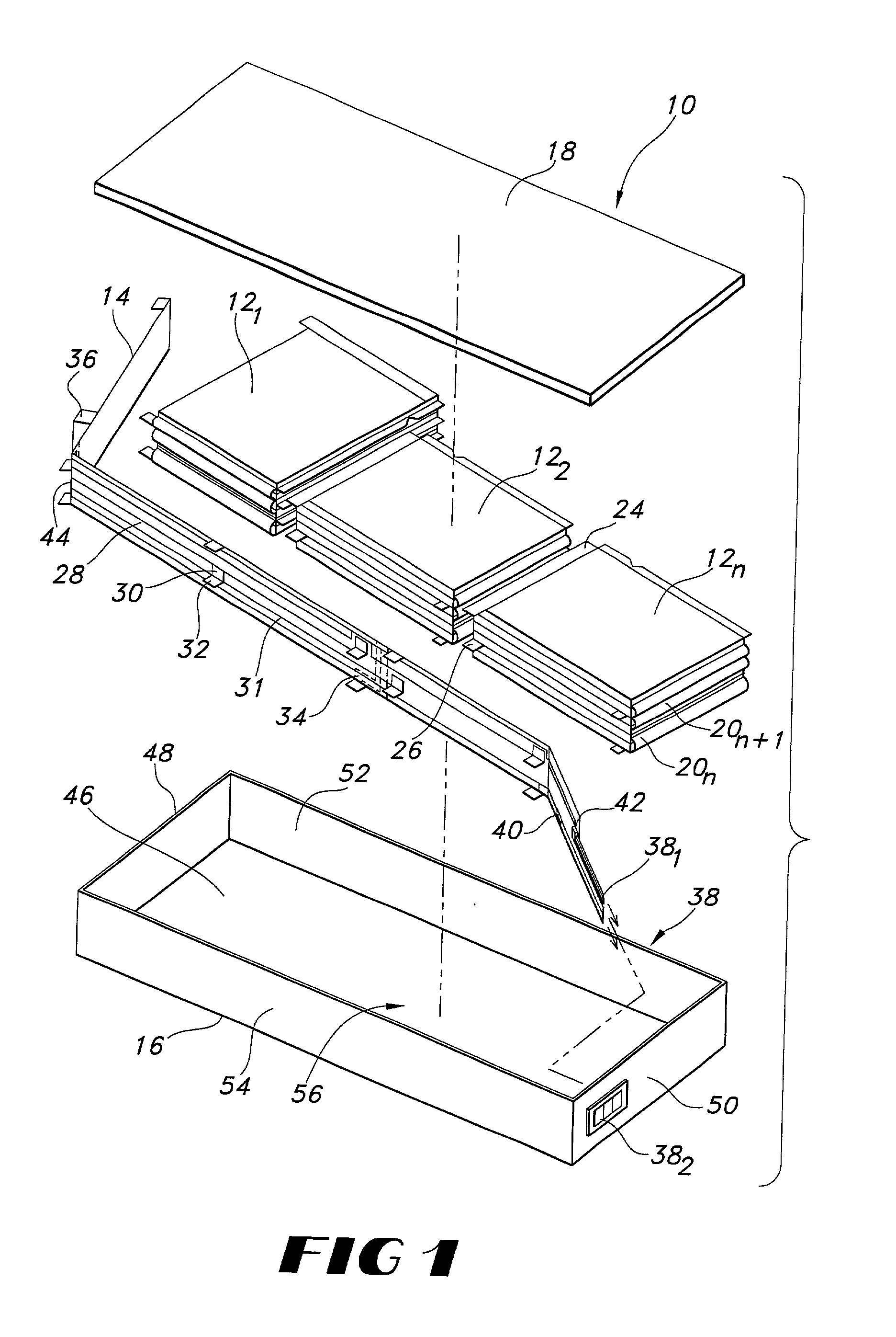
[0009] In a second aspect of the present invention, a pair of terminals associated with a battery unit are located on opposing sides of the battery unit, allowing the battery unit to be rotated one relative to an adjacent one and placed directly thereon. The process can be repeated to form battery modules. This arrangement allows a compact stacking of battery units.
[0011] In a third aspect of the present invention, a terminal for a battery unit includes a region that contains through apertures along a length dimension of the terminal. The apertures allow an adhesive or the like to flow through the apertures from a first side to a second side of the terminal to thereby form an improved seal. Additionally, in a preferred embodiment, a convoluted arrangement of apertures is used which presents a corresponding convoluted edge path. Such a path would require an electrolyte solution to travel a further distance before it could leak through the individual battery cell package, thereby reducing or eliminating the occurrence of leaking.

Problems solved by technology

However, these packages are heavy and expensive, which are disadvantages.
One of the problems involves leaking of the electrolyte solution at a seal point of the terminal to the package.
Another problem relates to the orientation of the terminals on the same side.
Specifically, the terminals are arranged to exit on the same side of the package and are adjacent to each other, making it difficult to electrically connect the packages in a compact configuration.

Method used


Image

  • Battery pack having perforated terminal arrangement
  • Battery pack having perforated terminal arrangement
  • Battery pack having perforated terminal arrangement

Examples


first embodiment

[0045] In a first embodiment, apertures 99.sub.a in region 98.sub.a are arranged in a repeating pattern and comprise a standard slot, I-shape through aperture. This allows adhesive to flow therethrough.

second embodiment

[0046] FIG. 6 shows second region, designated 98.sub.b. The second region 98.sub.b contains apertures 99.sub.b cut through terminal 24. In the illustrated embodiment, apertures 99.sub.b run substantially the length of terminal 24. Packaging envelope 80 seals to itself through the apertures of second region 98.sub.b at the sides 84, 86 because of the hot melt adhesive flows from above and below the apertures 98.sub.b to adhere to itself. The apertures 98.sub.b reduce or eliminate leaks of electrolyte solution from bicells 78 in at least two ways. First, the apertures 98.sub.b allow packaging envelope 80 to more effectively seal because the hot melt adhesive binds with itself. Second, the design of the apertures 98.sub.b creates a convoluted path by which the electrolyte solution must travel in order to leak from bicell 78.

[0047] FIG. 7 shows an enlarged view of a repeating pattern of apertures 98.sub.b referred to in the encircled region designated "7" in FIG. 6. FIG. 7 shows a first...


PUM

PropertyMeasurementUnit
electrically conductiveaaaaaaaaaa
electrical connectionaaaaaaaaaa
electrical insulatingaaaaaaaaaa

Abstract

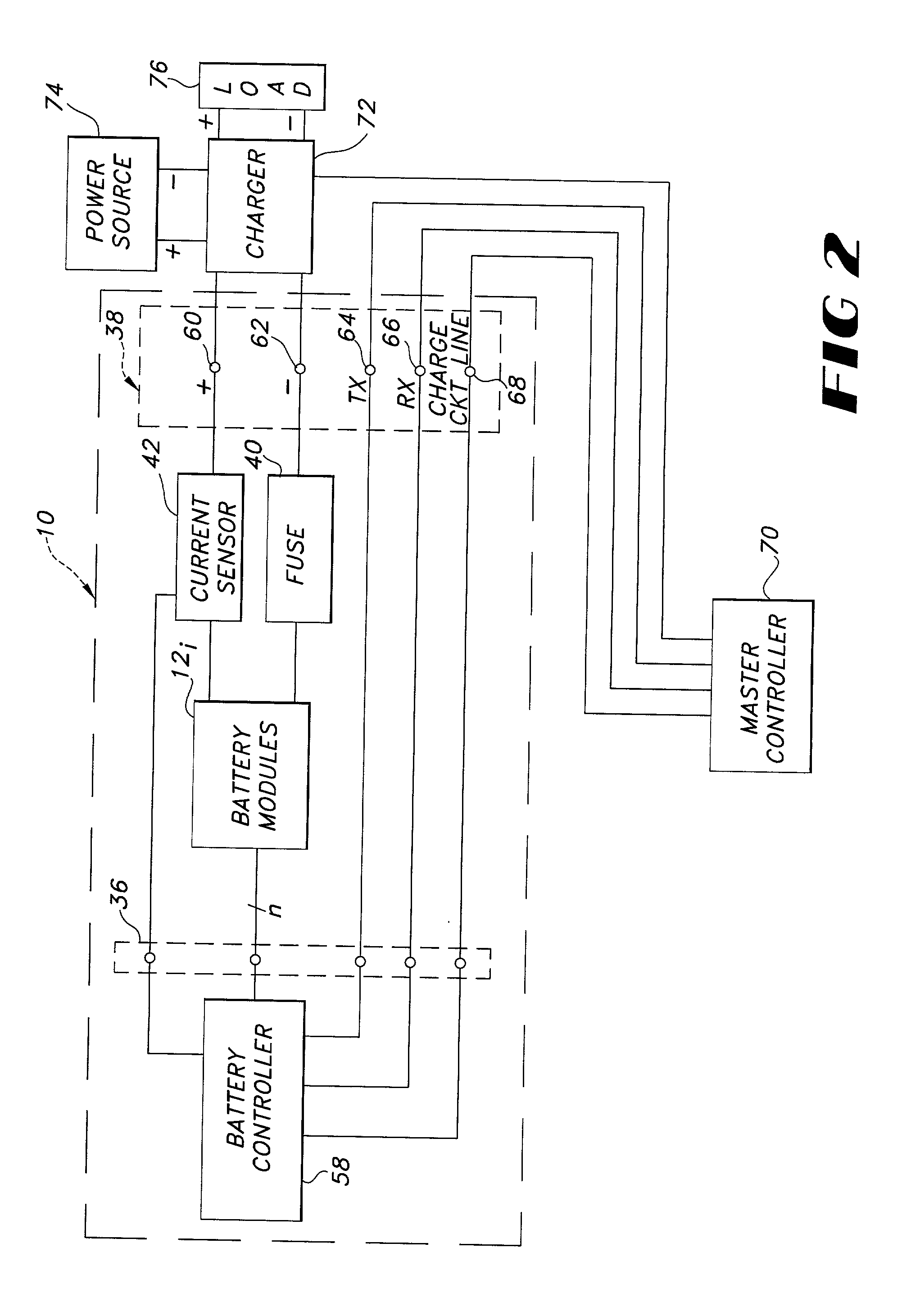
A battery pack containing a plurality of battery modules, said modules comprising a plurality of individual battery units, said battery units comprising a plurality of biceps with opposing terminals. The battery modules are connected in series by use of a flexible circuit and by opposing positive and negative terminals of each battery unit. The terminals of each battery unit contain a region of apertures which allow the adhesive of the packaging material to seal more effectively, thereby eliminating or reducing the amount of leakage from an individual battery unit.

Description

[0001] 1. Technical Field[0002] The present invention relates to battery packs and components thereof.[0003] 2. Description of the Related Art[0004] Conventional lithium polymer soft pack batteries use prismatic or cylindrical cans or rectangular boxes as a package for the battery cells as seen by reference to U.S. Pat. No. 5,639,571 issued to Waters, et al. However, these packages are heavy and expensive, which are disadvantages. In addition, conventional lithium polymer soft pack batteries further use nickel, copper or aluminum terminals to carry current through the package seal to the outside for connection to an overall package connector. These terminals are arranged to exit the same side of the package and are adjacent to each other. The foregoing "same-side" arrangement, however, has shortcomings.[0005] One of the problems involves leaking of the electrolyte solution at a seal point of the terminal to the package. Another problem relates to the orientation of the terminals on ...

Claims


Application Information

Patent Timeline
Patent Type & Authority Applications(United States)
IPC IPC(8): G11B23/50H01M10/052H01M10/42H01M50/211H01M50/227H01M50/278H01M50/284H01M50/296H01M50/528H01M50/534
CPCG11B23/505H01M2/0287H01M2/1022H01M2/22H01M2/26H01M10/052H01M10/425Y02E60/10H01M50/124H01M50/528H01M50/278H01M50/284H01M50/296H01M50/227H01M50/534H01M50/211
Inventor BENSON, MORGAN REYWENDLING, ROBERT THOMASCOCHRAN, STEVEN D.
Owner ENERDEL
Learn More