Ventilation system for malodorous air removal

Inactive Publication Date: 2002-12-26
HASHEMI AMIN H
View PDF0 Cites 79 Cited by
  • Summary
  • Abstract
  • Description
  • Claims
  • Application Information

AI Technical Summary

Benefits of technology

[0037] In this embodiment, the ventilation apparatus may further include a wall bracket affixed on the wall behind the tank. The wall bracket defines a slot, which is shaped and sized to allow the second flat end of the female air conduit to be snugly inserted therethrough. The slot is placed in alignment with the hole. The first flat end of the male air conduit is inserted into the opening of the second flat end, preferably passing the slot into the wall area. Additionally, the wall bracket may define a lower flange and an upper flange for pressing the flat ends tightly together and to minimize any air leakage. Alternatively, the perimeter of the slot can be sealed with any suitable caulking material.
[0060] The optional light unit includes a reflector plate, a light bulb, a second electrical outlet for supplying electricity to the light bulb, and a shield for protecting the light bulb. The reflector plate can fit into the insert slot and can be secured to the grille plate. The light bulb includes a socket secured to the reflector plate. The socket has a connecting plug for inserting into the second electrical outlet. The second electrical outlet may be connected to a second switch that can be operated by a user. Optionally, the second electrical outlet may be electrically connected to the first electrical outlet, and both outlets are connected to a switch that a user can operate. In this way, the user can turn on the fans and the light at the same time.
[0072] It is one object of the present invention to provide a toilet system having a ventilation apparatus for removing odorous air from the toilet bowl without creating negative pressure in the water tank. Another objective is to provide an automatic flushing mechanism that can be retrofitted to a traditional flush toilet system. In addition, a further objective is to provide a fan system that can efficiently drive the odorous air or steam from the bathroom for discharging outside.

Problems solved by technology

Withdrawing the air from the airspace in a tightly closed water tank may create suction pressure especially when the toilet is flushed.
The inefficiency in withdrawing the odorous air from the sleeve into the exhaust pipe can be a drawback with this system, because only low air pressure can be applied so that the water within the sleeve is not also withdrawn.
A drawback in this system rests on the efficiency of the system, which in turn, is limited by the volume of odorous air that can be filtered through the system.
One drawback of this system is the requirement of a specially designed toilet bowl and water tank.
A major drawback for the weight activating flushing mechanism is that it does not operate when the user does not sit down on the seat.
Possible concerns of these systems are in the limitation of fitting all the parts into an existing toilet system and the need to modify the water tank and the toilet lid for positioning the motion-sensing device.

Method used


Image

  • Ventilation system for malodorous air removal
  • Ventilation system for malodorous air removal
  • Ventilation system for malodorous air removal

Examples


Embodiment Construction

[0140] For the purposes of promoting an understanding of the principles of the invention, reference will now be made to the embodiments illustrated in the drawings and specific language will be used to describe the same.

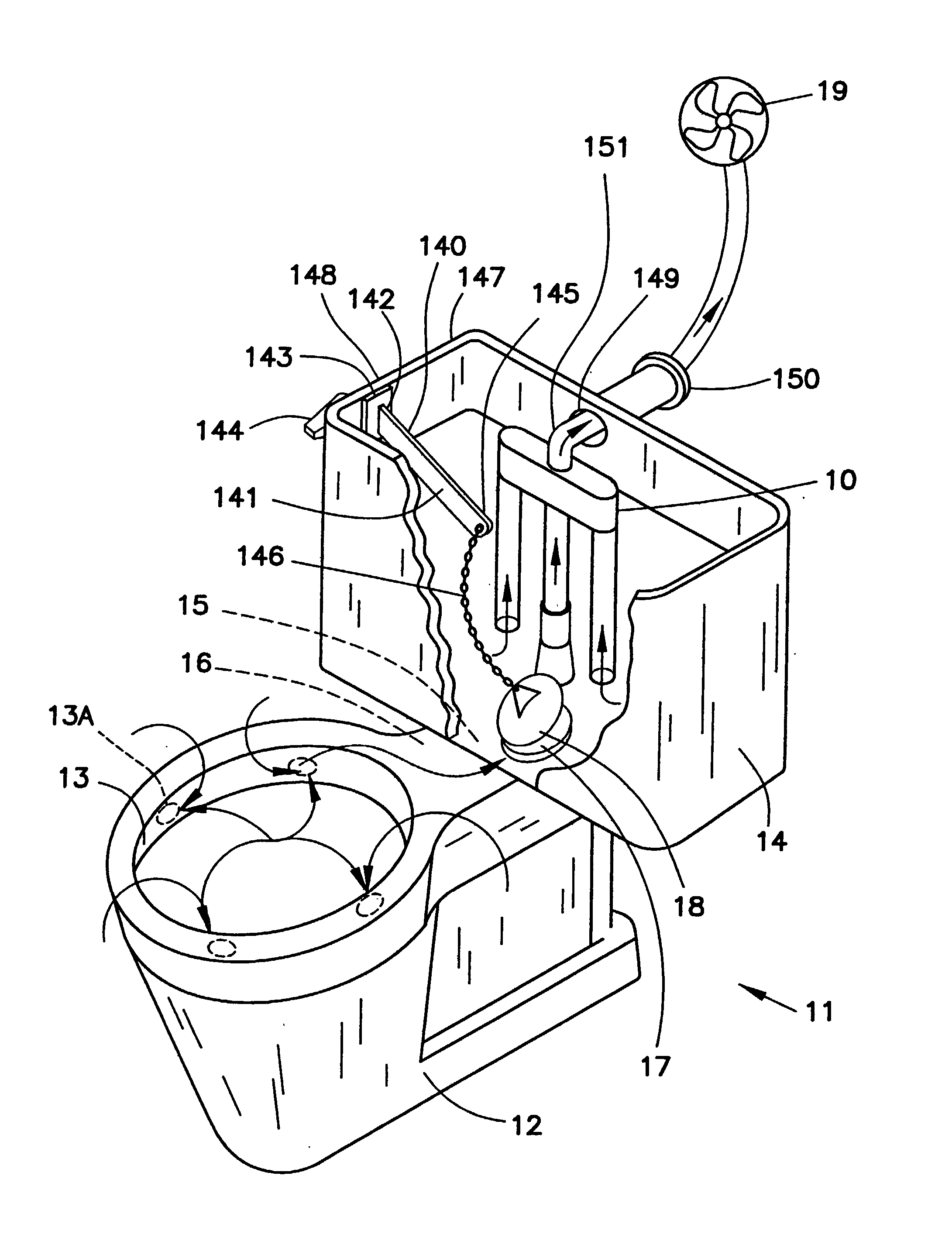
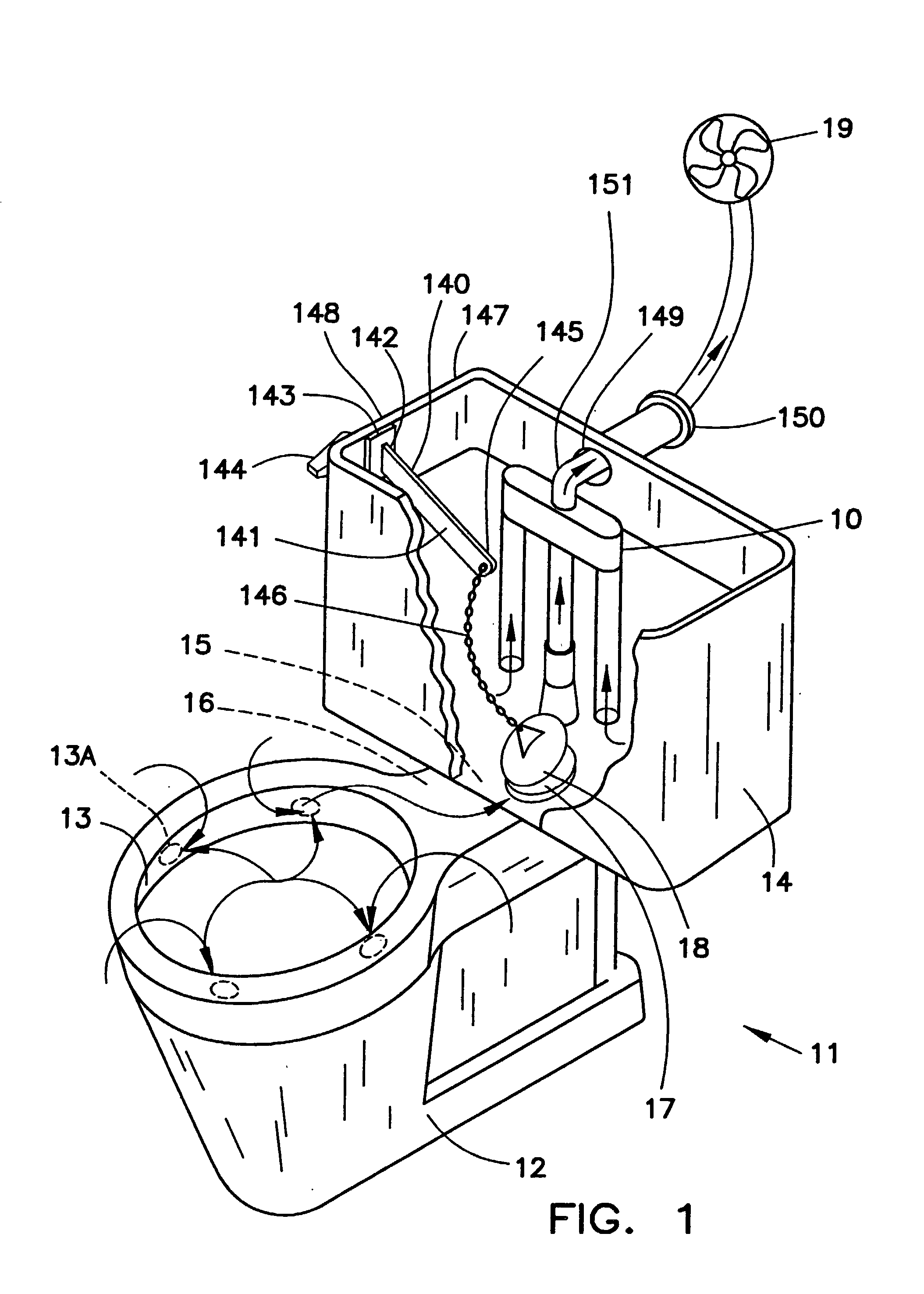
[0141] As shown in FIG. 1, the present invention contemplates ventilation apparatus 10 for eliminating odor from traditional flush toilet 11. Toilet 11 generally includes toilet bowl 12 with rim 13 defining a plurality of holes 13A, water tank 14 with lid 6, discharge conduit 15 connecting bowl 12 and tank 14, and passageway 16 providing communication between tank 14, discharge conduit 15, and rim 13. Toilet 11 includes flush valve 17 disposed above discharge conduit 15, flush valve 17 having flapper 18 for opening and closing passageway 16 to allow movement of water from tank 14 into discharge conduit 15, water in conduit 15 is distributed along passageway 16 within rim 13 and into bowl 12 through the plurality of holes 13A.

[0142] According to one aspect of the pres...


PUM


Abstract

An odor evacuation and mitigation system for a bathroom space including a central evacuation fan system, an odor evacuation system for a toilet having a toilet bowl, an automatic flushing system, and a steam and moisture ventilation system. The fan system includes an enclosure having a motor and fan therein and connected to an exhaust hose for expelling odors. The odor evacuation system for a toilet includes a flush valve in communication with a pipe, connected to an external suction device for removal of odors, through an overflow pipe and an evacuation pipe. The automatic flushing system includes a sensor connected to a servomotor for rotation of an actuation lever connected to a flush valve. The steam ventilation system includes a manifold body disposed over a shower enclosure and having a grille through which air flows into the manifold body and outward through an externally extending hose.

Description

CROSS-REFERENCE TO RELATED PCT AND U.S. APPLICATIONS[0001] This is a continuation-in-part application of co-pending PCT Application Serial No. PCT / US01 / 50232, filed Dec. 20, 2001, and designating the United States, which is a continuation-in-part of co-pending U.S. patent application Ser. No. 09 / 742,771, filed Dec. 20, 2000.[0002] 1. Field of the Invention[0003] The present invention relates generally to room ventilation systems.[0004] 2. Background Art[0005] Various types of toilet assemblies having an odor mitigation system are known in the art. An efficient way for odor removal from a water closet is by drawing odorous air from the toilet bowl through the flush rim. Ventilation systems utilizing this air passage have been disclosed in U.S. Pat. Nos. 3,703,010, 4,165,544, 4,583,250, 4,989,276, 5,321,856, and 5,617,590.[0006] The system described in the '010 patent includes a suction means in air communication with the airspace between the water within the water tank and the lid of...

Claims


Application Information

Patent Timeline
IPC IPC(8): E03D5/092E03D5/094E03D5/10E03D9/052
CPCE03D5/092E03D9/052E03D5/10E03D5/094
Inventor HASHEMI, AMIN H.
Owner HASHEMI AMIN H
Why Eureka
Try Eureka