
Robot hand member and method of producing the same

a technology of hand parts and hand parts, which is applied in the field of hand parts of robots, can solve the problems of increasing deflection due to its own, affecting the design of the robot and the cost, and increasing vibration

Inactive Publication Date: 2002-12-05
NIPPON MITSUBISHI OIL CORP
View PDF6 Cites 8 Cited by
  • Summary
  • Abstract
  • Description
  • Claims
  • Application Information

AI Technical Summary

Benefits of technology

[0014] According to the above constitution, it is possible to form a robot hand member with a small number of production processes and a low production cost. By using the fiber reinforced plastic, further, it is possible to produce a robot hand member which is lighter in weight than the one made of metal, having excellent flatness, flexural rigidity, vibration attenuation characteristics and heat resistance. Further, since the core member is removed to form a hollow structure, it is possible to further improve the light in weight, and besides, it is possible to arrange, in the hollow portion, the devices, wirings, pipe arrangement and the like necessary for the functions of the robot hand. Further, since the core member can be repetitively used, it is possible to lower the material cost.
[0033] Further, the step of winding or adhering prepreg sheets in a multi-layer may include a step of winding a cloth prepreg sheet on the outermost layer on which the prepreg sheets are wound or adhered. According to this constitution, the fluffing in a subsequent working of cutting or polishing is reduced. Thus, the working performance as a member is improved, and the product that is finally obtained exhibits improved appearance.

Problems solved by technology

At the present time where the size is ever increasing, however, the solid member of CFRP causes the robot hand itself to become heavy resulting in an increased deflection due to its own weight.
Further, as the robot hand becomes heavy, a load on a robot drive system is increased, thereby affecting the design of the robot and the cost thereof.
When a long robot hand member is cantilevered, in particular, deflection at an end thereof is increased, and vibration is increased when the workpiece is supported, causing a trouble in supporting or conveying the workpiece.
Therefore, a period of time required for the production becomes longer and the cost for the production becomes high.
This method, however, requires a step of laminating prepreg sheets, a step of forming the CFRP plates by the thermosetting, and a step of adhering the CFRP plates, and also there is such a problem that the portions where the CFRP plates are adhered have the low strength against a load.
If the robot hand member has a hollow structure, however, the central portion is likely to be dented.
According to this method, however, there are disadvantages in that a complicated operation is required for adhering the FRP plates of the four surfaces at the edges thereof, the dimensional precision is decreased, the strength at the adhered portions is likely to be decreased, and the number of processes are increased since the FRP plates that have been formed by using the prepreg sheets are joined together.
In particular, since the outer mold is usually larger and more expensive than the inner mold, a high cost is necessary to separately prepare the outer molds or to provide various outer molds to meet the shapes of the robot hand members.
That is, in the case of the robot hand member of the hollow structure, there are disadvantages in that deformation with the time elapse such as denting in the central portion accompanying the use is caused, or, it is forced to modify the design concerning the portions where the grooves and holes are formed when replacing the conventional robot hand member made of the solid material by a new one.

Method used


Image

  • Robot hand member and method of producing the same
  • Robot hand member and method of producing the same
  • Robot hand member and method of producing the same

Examples


Embodiment Construction

(Lamination of a Hollow CFRP Structure):

2TABLE 2 Lamination of a hollow structure (square pipe: 12 mm thickness, CFRP plate: 2.55 mm thickness) Laminating Number of Total Thickness direction lamination thickness Kinds of prepreg (mm / sheet) (degree) (sheet) (mm) Cloth prepreg 0.25 0 / 90 1 0.25 Prepreg-A 0.22 0 5 1.1 Prepreg-B 0.20 90 6 1.2 Core member 6.9 -- 1 6.9 (aluminum et al) Prepreg-B 0.20 90 6 1.2 Prepreg-A 0.22 0 5 1.1 Cloth prepreg 0.25 0 / 90 1 0.25 Total 24 12.0 Deflection due to 0.47 own weight (mm) Weight (kg) 0.75 Thickness (mm) Longitudinal 12.1 (front), 11.8 (middle), 12.1 (rear) direction Width direction 12.0 (left), 11.8 (middle), 12.0 (right)

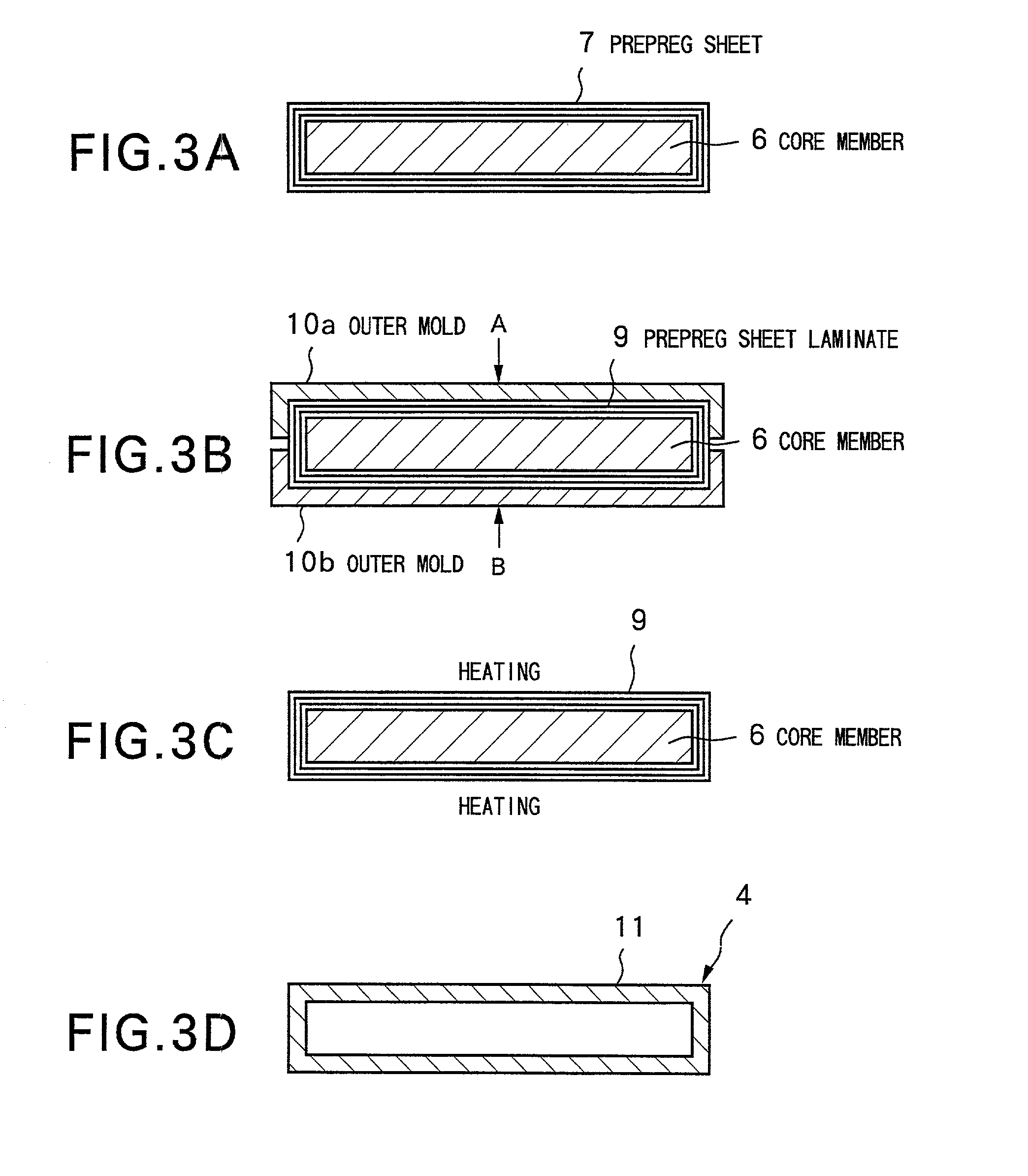
[0126] This Example 1 deals with the robot hand member 4 of a hollow structure shown in FIG. 2 produced by the first production method shown in FIG. 3. Table 2 shows numerical values involved in the production. This Example uses a total of six layers. That is, there are used cloth prepregs in which carbon fibers are oriented in th...


PUM

PropertyMeasurementUnit
Angleaaaaaaaaaa
Angleaaaaaaaaaa
Angleaaaaaaaaaa

Abstract

A robot hand member mounted on an arm unit of an industrial robot and a method of producing the same, wherein there are successively executed a step of laminating prepreg sheets each containing a reinforcing fiber on the outer peripheral surface of a core member having a predetermined shape in cross section, a step of heating the laminated prepreg sheets to a predetermined temperature to thermally set, to form a fiber reinforced plastic, and a step of removing the core member from the fiber reinforced plastic to obtain a hollow structure.

Description

[0001] 1. Field of the Invention[0002] The present invention relates to a robot hand member to be mounted on an arm unit of an industrial robot and to a method of producing the same. More specifically, the invention relates to a robot hand member made of fiber reinforced plastic obtained by thermally setting a prepreg sheet containing a reinforcing fiber laminated on the outer peripheral surface of a core member, and to a method of producing the same.[0003] 2. Description of the Related Art[0004] Glass substrates that have been produced in increased sizes accompanying a widespread use of liquid crystal displays (LCDs), have required an increase in size of a substrate-conveyer robot hand to be used in the production process of precision parts such as LCDs, plasma display panels (PDPs), silicon wafers and the like. Further, a robot hand for conveying large plasma display panels (PDPs) has a size larger than that of the robot hand for conveying the LCDs.[0005] Metals such as steel, sta...

Claims


Application Information

Patent Timeline
IPC IPC(8): G02F1/13B29C70/34
CPCB29L2022/00B29C70/345G02F1/13
Inventor KOBAYASHI, TAKASHIAOYAGI, KENICHIUCHIDA, DAISUKE
Owner NIPPON MITSUBISHI OIL CORP
Learn More