Stator for rotary machine and method of manufacturing the stator

a stator and rotary machine technology, applied in the direction of stator/rotor body manufacturing, magnetic circuit shape/form/construction, applying solid insulation, etc., can solve the problems of increased cost, increased material cost of insulating paper 19, increased cost, etc., and achieve high insulation and cooling performance, simple production method, the effect of high quality

Inactive Publication Date: 2002-09-19
MITSUBISHI ELECTRIC CORP
View PDF4 Cites 46 Cited by
  • Summary
  • Abstract
  • Description
  • Claims
  • Application Information

AI Technical Summary

Benefits of technology

[0014] This invention has been achieved in the light of the aforementioned problems, and it is an object of the invention to provide a stator for a rotary machine and a method for manufacturing the stator, in which the stator has a high insulation and cooling performance, and can be produced in simple manner, with high quality and lower costs.

Problems solved by technology

However, in the conventional alternator for the vehicle, since the insulation between the stator coil group 16 and the stator iron core 15 was made by the insulating paper 19, as described above, there was a problem that the material cost of the insulating paper 19 was taken, a greater number of steps were required, and the costs were increased.
Also, there was a further problem that the insulation process such as coating was required as another step on a portion where the iron core portion was exposed, thereby increasing the number of steps.
At a step of forming the stator iron core 15 cylindrically, an excessive stress occurs in the teeth 15c of the stator iron core 15, and a laminated steel plate making up the teeth 15c is deformed and shifted circumferentially on the inner diameter side of the stator iron core 15, disordering a magnetic circuit, resulting in a problem of lower output voltage.
Accordingly, a contact occurs between the opening edge of the axial end face for the stator iron core 15 and the stator coil group 16, and the insulating paper and the insulation film for the stator coil group 16 are exfoliated, resulting in a problem of causing a pressure-proofing failure.
Therefore, due to an insulation failure caused by a dislocation when inserting the stator coil group 16, or the water content permeating into the gap, or a bad thermal conduction (coolness) between the stator coil group 16 that is a heat generating body and the stator iron core 15, there was a problem that the alternator for vehicle was degraded in quality.

Method used


Image

  • Stator for rotary machine and method of manufacturing the stator
  • Stator for rotary machine and method of manufacturing the stator
  • Stator for rotary machine and method of manufacturing the stator

Examples


embodiment 1

[0059] (Embodiment 1)

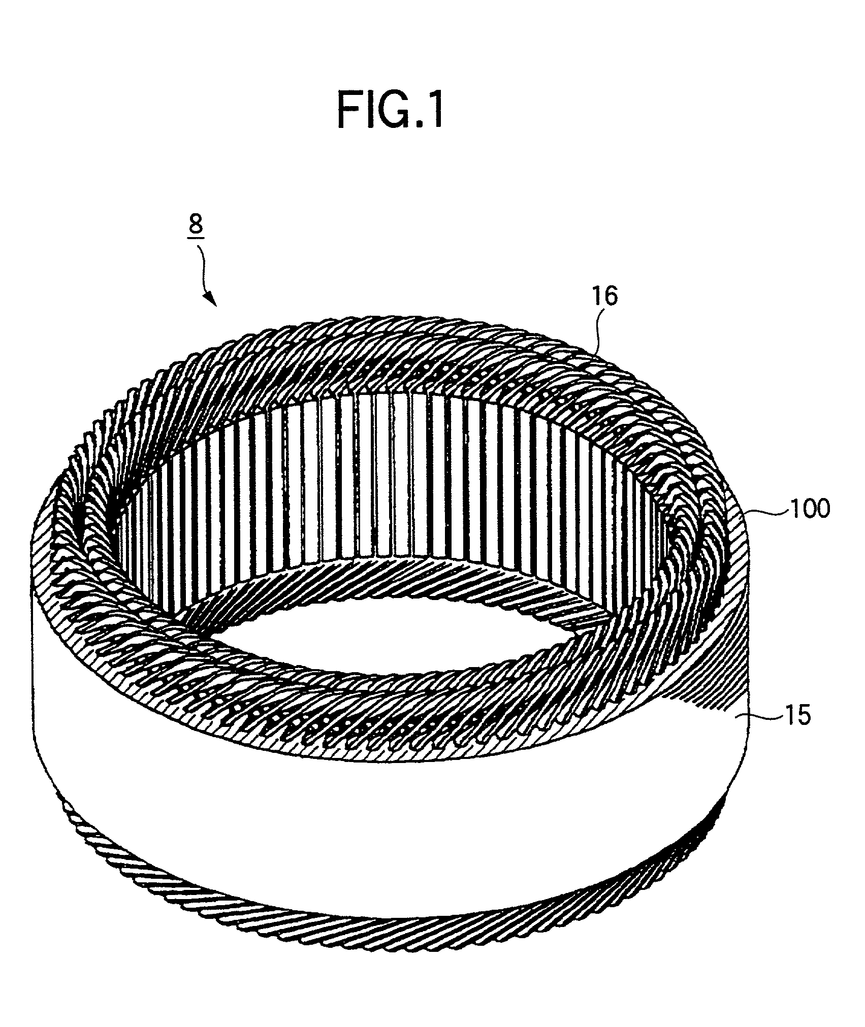
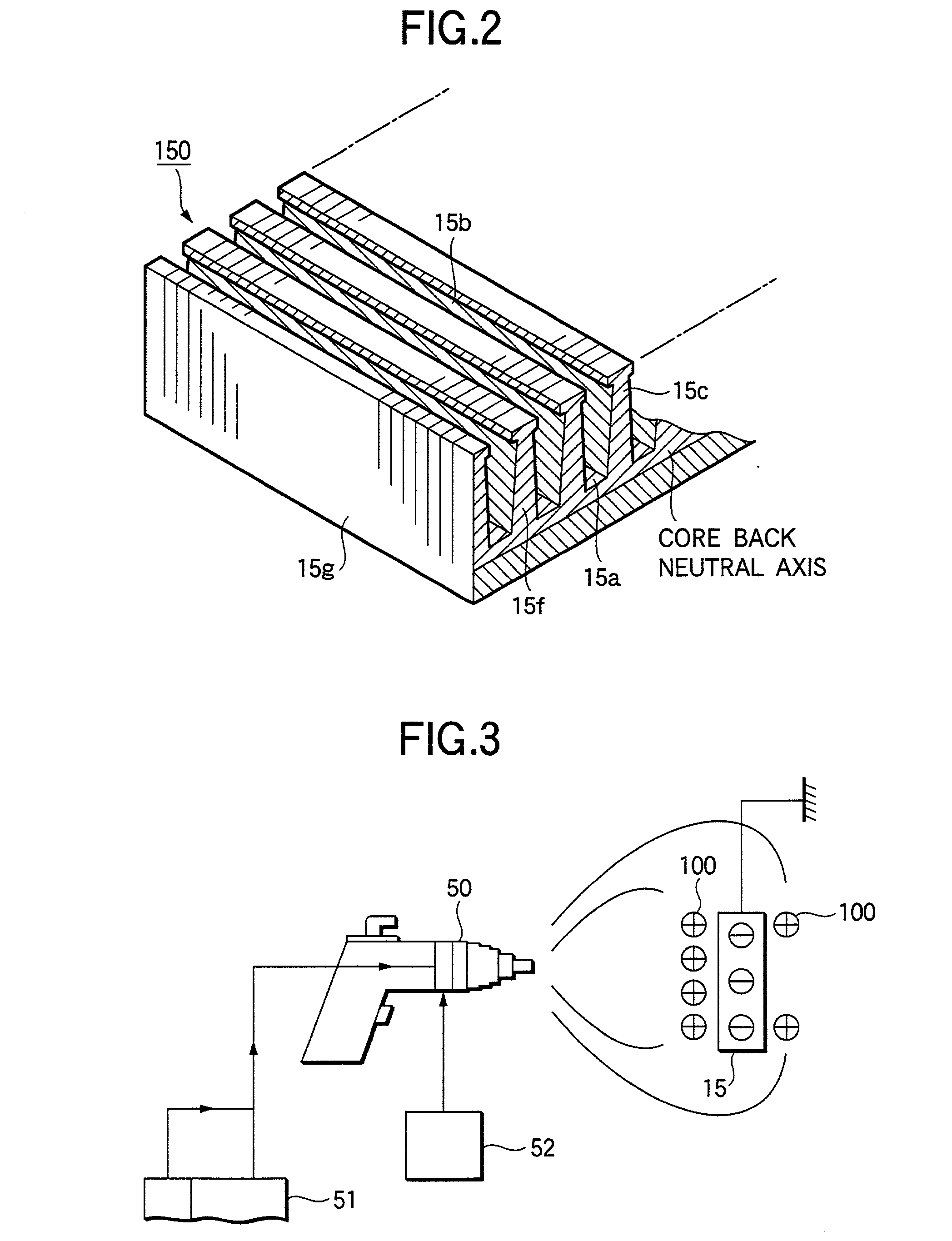
[0060] FIG. 1 is a perspective view showing a stator for a rotary machine according to an embodiment 1 of this invention. FIG. 2 is a perspective view showing a laminated iron core before being molded cylindrically into the stator as shown in FIG. 1. The stator 2 has a stator iron core 15 with SPCC of 0.35 mm laminated, and a stator coil group 16 secured to this stator iron core 15. The stator coil group 16 is composed of a long coil element wire 30 bent like a thunder, as explained in the prior art. In the prior art, an electrical insulation between the stator coil 16 and an inner wall face of a slot 15a was made by the insulating paper 19. However, in this invention, the insulating paper 19 is dispensed with, and an insulating resin 100 is applied on the stator iron core 15 to provide insulation between the stator coil 15 and the inner wall face of the slot 15a.

[0061] Herein, the application of the insulating resin 100 is desirably made by electrostatic powder...

embodiment 2

[0073] (Embodiment 2)

[0074] FIG. 6 is a perspective view showing a stator for a rotary machine according to an embodiment 2 of this invention. FIGS. 7 and 8 are process views of inserting a coil group into a stator iron core. In this embodiment, unlike the above embodiment 1, there are three pairs of stator coil groups 16 composed of a long copper wire 30 having a rectangular cross section of 1.6 mm long.times.1.4 mm wide.times.R 0.2 mm at corner part.

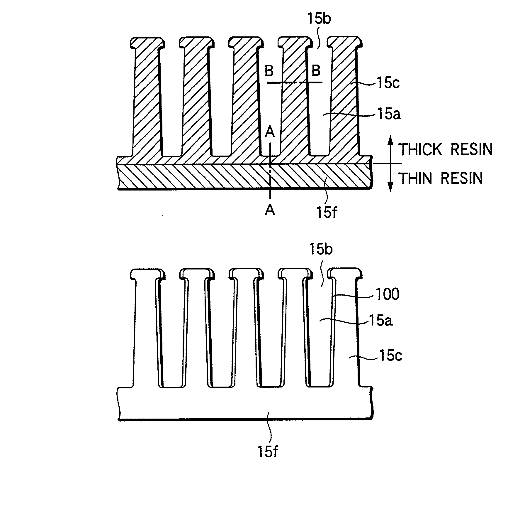
[0075] FIG. 9 is an external view and a partial cross sectional view of a stator iron core for a rotary machine in a circumferential direction of slot, according to the embodiment 2 of this invention. As shown in FIG. 9, the insulating resin 100 is coated to be thinner on the inner wall face of the slot 15a on the outer circumferential side of the stator iron core than any other portion. This is because when the straight laminated iron core 150 is formed cylindrically, the inner wall face of the slot 15a on the outer circumferential si...

embodiment 3

[0080] (Embodiment 3)

[0081] FIG. 11 is a circumferential cross sectional view showing the teeth in the stator iron core of the stator for rotary machine according to an embodiment 3 of this invention. As shown in FIG. 11, an end face 15f of the stator iron core 15 is formed irregularly. Thereby, the end face 15f of the stator iron core 15 and the insulating resin 100 are contacted more intimately, and the exfoliation of the insulating resin 100 can be prevented when the stator coil 16 is inserted into the slot 15a. Also, the formation of irregular shape may be made in a surface treatment process such as a shot process.

[0082] The same effects can be obtained by forming irregularities on the inner wall face of a slot 24 as shown in FIG. 11. The formation of irregularities can be made, for example, by alternately laminating a laminated plate 360d having a larger size in the circumferential direction of the stator iron core and a laminated plate 361d having a smaller size, when the stat...


PUM

PropertyMeasurementUnit
Diameteraaaaaaaaaa
Shapeaaaaaaaaaa
aaaaaaaaaa

Abstract

A stator for a rotary machine includes a rotor 7 and a stator 8 having a stator iron core 15 disposed oppositely around the outer circumference of the rotor 7 and a stator coil 16 fitted around the iron core 15, wherein the iron core 15 has a laminated iron core 150 with plural axially extending slots 15a formed circumferentially at predetermined pitches, an insulating resin 100 is coated on an axial end face 15f of the iron core 15 and an inner wall face of a slot 15a in the laminated iron core 150 to provide insulation between the iron core 15 and the stator coil 16, and the iron core is cylindrically shaped by bringing both circumferential end portions 15g of the laminated iron core 150 into contact to bend the laminated iron core 150 so that an opening face 15b of the slot 15a is directed inside.

Description

BACKGROUND OF THE INVENTION[0001] 1. Field of the Invention[0002] The present invention relates to a stator for a rotary machine that is driven by an internal combustion engine for the vehicle, for example, and a method for manufacturing the stator.[0003] 2. Description of the Related Art[0004] FIG. 13 is a perspective view showing the conventional rotary machine (alternator for vehicle) as disclosed in U.S. Pat. No. 3078288, for example. In FIG. 13, a rotor 7 of landau type is rotatably attached via a shaft 6 within a case 3 composed of a front bracket 1 and a rear bracket 2, and a stator 8 is supported on an inner wall face of the case 3 to cover the outer circumferential side of the rotor 7. The shaft 6 is rotatably supported by the front bracket 1 and the rear bracket 2. A pulley 4 is secured at one end of this shaft 6 to allow a rotational torque of the engine to be transmitted via a belt (not shown) to the shaft 6. A slip ring 9 for supplying a current to the rotor 7 is secure...

Claims


Application Information

Patent Timeline
IPC IPC(8): H02K1/16H02K1/04H02K3/04H02K3/34H02K3/38H02K15/02H02K15/085H02K15/10H02K15/12H02K19/22
CPCH02K1/16H02K3/345H02K3/38H02K15/024H02K15/12Y10T29/49009H02K15/10
Inventor OKETANI, NAOHIROTAKIZAWA, TAKUSHIKATAYAMA, HIROKIOOHASHI, ATSUSHIASAO, YOSHIHITO
Owner MITSUBISHI ELECTRIC CORP
Why Eureka
Try Eureka