
Geometrically optimized fast neutron detector

a fast neutron detector and geometrical optimization technology, applied in the direction of instruments, radiation measurement, measurement devices, etc., can solve the problems of reducing the gamma ray rejection capability of the detector, cylinders cease to be efficient sources of recoil protons, and the thickness of plastic cylinders is too much

Inactive Publication Date: 2002-09-19
PRECISION ENERGY SERVICES
View PDF0 Cites 13 Cited by
  • Summary
  • Abstract
  • Description
  • Claims
  • Application Information

AI Technical Summary

Benefits of technology

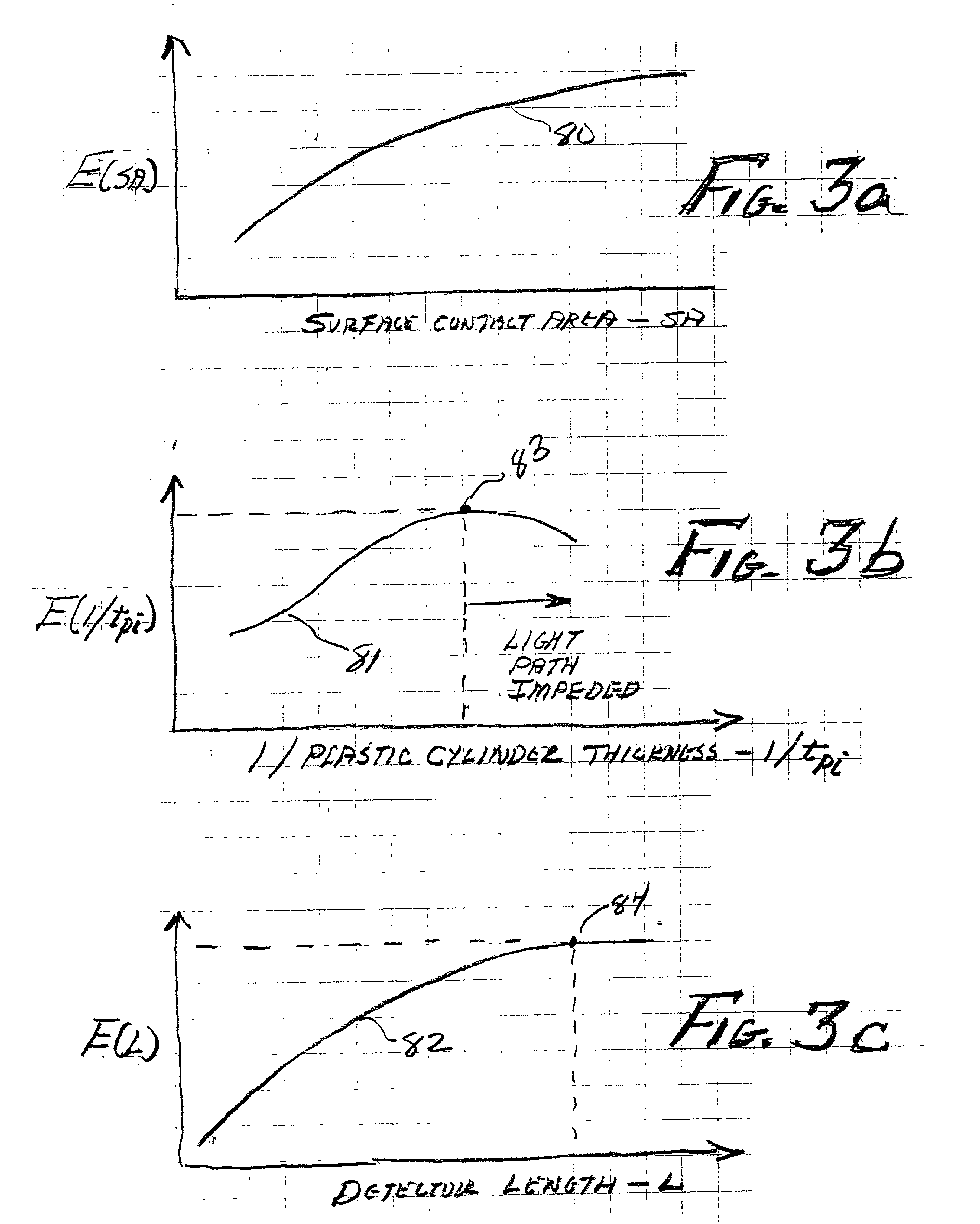
[0031] For a given overall detector diameter D, efficiency can generally be increased by decreasing the radial wall thickness of the ZnS and plastic cylinders, thereby increasing the ZnS-plastic surface area. If, however, the wall thickness of the plastic cylinders is decreased too much, the cylinders cease to become an efficient source of recoil protons, and further cease to become a scintillation "light path" to the PM photocathode. Furthermore, if the radial wall thickness of the ZnS cylinders is decreased too much, the cylinders will not scintillate all entering recoil protons. Stated another way, the ZnS and plastic cylinder wall thicknesses for maximum detector efficiency is a "trade-off", and these dimensions must be optimized for a given detector diameter D. Detector efficiency can also be increased by increasing the length L of the detector. Length is also a trade-off parameter in that excessive length can decrease the detector's gamma ray rejection capability, and further decrease the efficiency of the plastic annuli as light paths to the PM photocathode.

Problems solved by technology

If, however, the wall thickness of the plastic cylinders is decreased too much, the cylinders cease to become an efficient source of recoil protons, and further cease to become a scintillation "light path" to the PM photocathode.
Length is also a trade-off parameter in that excessive length can decrease the detector's gamma ray rejection capability, and further decrease the efficiency of the plastic annuli as light paths to the PM photocathode.

Method used


Image

  • Geometrically optimized fast neutron detector
  • Geometrically optimized fast neutron detector
  • Geometrically optimized fast neutron detector

Examples


Embodiment Construction

[0051] A fast neutron detector suitable for use in borehole logging instruments must detect neutrons efficiently in the energy ranges from about 1 million electron volts (MeV) to 14 MeV, reject any response to accompanying radiation, be mechanically rugged, and operate at a temperature of about 175.degree. C. The combination of separate regions of activated ZnS scintillator and hydrogen rich plastic produces a suitable fast neutron detector when optically coupled to a photomultiplier (PM) tube. Energetic protons are produced by fast neutrons scattering from hydrogen within the plastic. A scintillation photon is produced when an energetic proton reaches the ZnS scintillator. Because the linear range of energetic protons is very short in both the scintillator and plastic materials, and because light must escape the optically cloudy ZnS region to be detected by the PM tube, the interface between the two materials is critical to the detector's fast neutron response. Therefore, the total...


PUM


Abstract

An improved fast neutron detector fabricated with alternating layers of hydrogenous, optically transparent, non scintillating material and scintillating material. Fast neutrons interact with the hydrogenous material generating recoil protons. The recoil protons enter the scintillating material resulting in scintillations. The detector is optically coupled to a photomultiplier tube which generates electrical pulses proportional in amplitude to the intensity of the scintillations, and therefore are an indication of the energy of the fast neutrons impinging upon the detector. Alternating layers of materials are dimensioned to optimize total efficiency of the detector, or to optimize the spectroscopy efficiency of the detector. The scintillating material is preferably ZnS, and the hydrogenous material is preferably plastic. The detector is ideally suited for well logging applications and fast neutron monitor applications.

Description

RELATED APPLICATIONS[0001] This application is related to application Ser. No. ------ entitled "Geometrically Optimized Fast Neutron Detector" and application Ser. No. ------ entitled "Geometrically Optimized Fast Neutron Detector".BACKGROUND OF THE INVENTION[0002] 1. Field of the Invention[0003] This invention is directed toward an improved fast neutron detector, and more particularly directed toward the optimization of the detector efficiency when used in logging of earth formations penetrated by a borehole and for a variety of applications.[0004] 2. Background of the Art[0005] In the context of this disclosure, "logging" is defined as the measure of a parameter of material penetrated by a borehole, as a function of depth within the borehole.[0006] There are many types or classes of borehole logging systems. These classes include, but are not limited to, electromagnetic, acoustic and nuclear systems. Each class of logging system typically comprises a "source" which emits energy in...

Claims


Application Information

Patent Timeline
IPC IPC(8): G01T3/06
CPCG01T3/06
Inventor ODOM, RICHARD C.TILLER, DONALD E.WILSON, ROBERT D.
Owner PRECISION ENERGY SERVICES
Learn More