
Alkaline battery

Inactive Publication Date: 2002-09-12
MURATA MFG CO LTD
View PDF1 Cites 41 Cited by
  • Summary
  • Abstract
  • Description
  • Claims
  • Application Information

AI Technical Summary

Benefits of technology

[0021] It is an object of the present invention to provide a highly reliable alkaline battery which is improved the above-mentioned problem.

Problems solved by technology

However, none of them can completely suppress the evolution of hydrogen gas which results from zinc or zinc alloy powder coming into contact with the current collector through alkaline electrolytic solution.
This creeping leads to the possibility of the electrolytic solution leaking out of the seal between the open end of the cathode can 1 and the anode cup 3 when pressure in the battery rises due to evolution of hydrogen gas for one reason or another.
Although the problem with creeping is solved as mentioned above, there still exists the possibility of hydrogen gas occurring when the coating layer 30 suffers defects such as pinholes, cracks, and contamination with impurities.
Such defects permit zinc or zinc alloy to come into electrical contact with the copper of the current collector through the electrolytic solution.
Thus this problem is not completely solved by the mercury-free anode structure.
In actual mass production, however, it is difficult to perform partial plating accurately in a limited region on the inside of the anode cup excluding the fold and the bottom of the fold.
There is the possibility that the copper surface of the anode cup (current collector) is oxidized by the plating solution during washing.
Difficulties are involved in applying to mass production the technology of preventing the evolution of hydrogen gas (H.sub.2) and suppressing the creeping up of the alkaline electrolytic solution.

Method used


Image

  • Alkaline battery
  • Alkaline battery
  • Alkaline battery

Examples


example 1

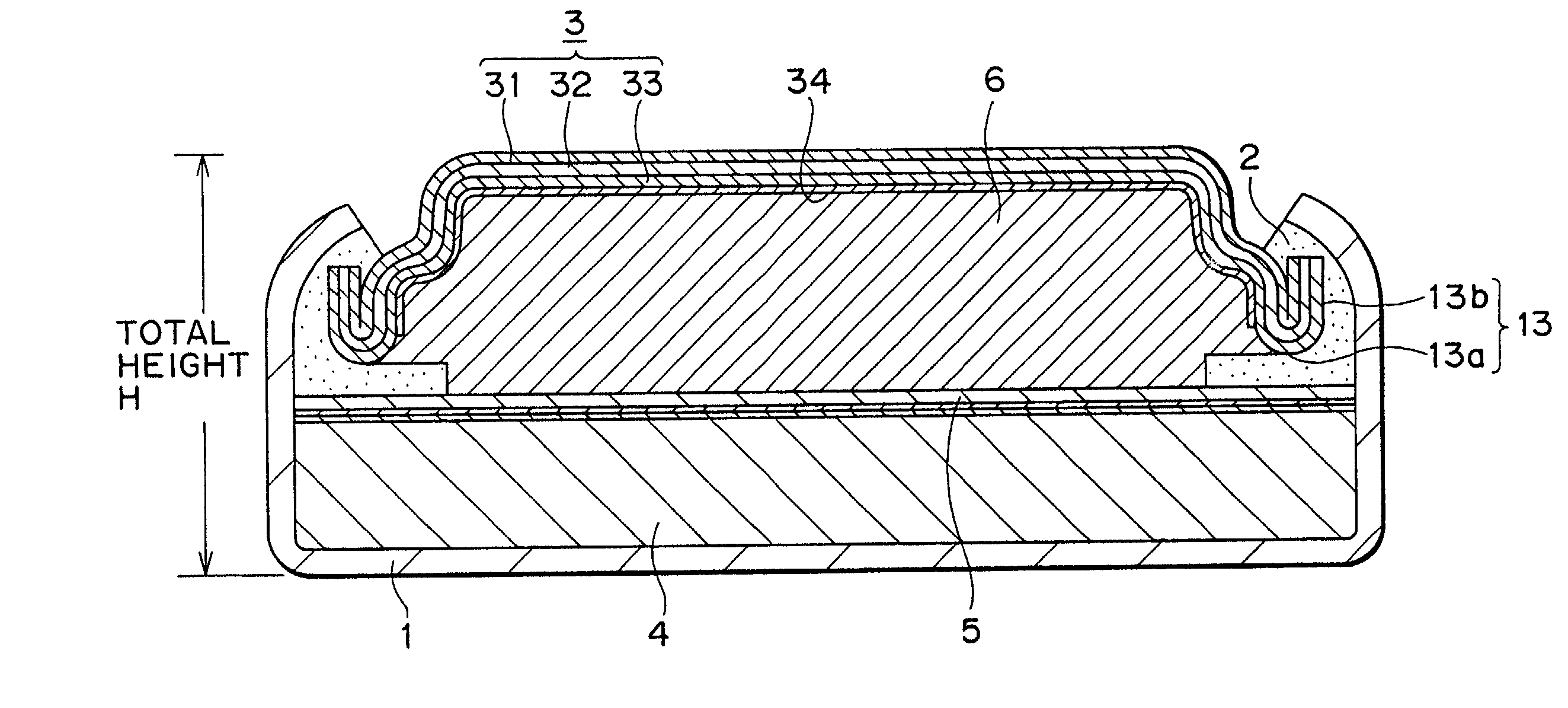
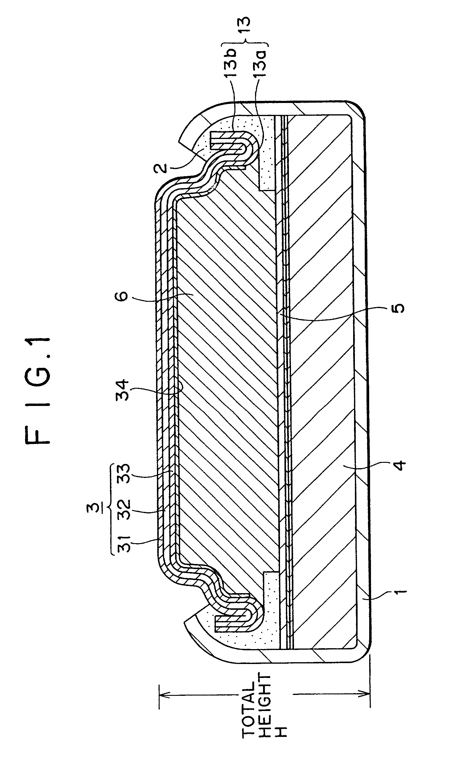
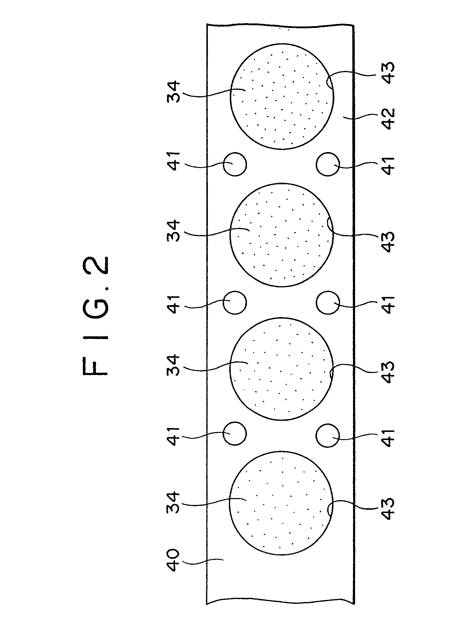
[0054] This example demonstrates an SR626SW battery constructed as shown in FIG. 1. First, the triple-layered metal sheet 40 (0.2 mm thick) was prepared which is composed of the nickel outer layer 31, the metal layer 32 of stainless steel (SUS 304), and the current collector layer 33 of copper, as shown in FIG. 2. Aligning holes 41 were formed in this layered metal sheet 40 to facilitate positioning at the time of making openings in a masking tape which will be described later and press-forming the anode cup.

[0055] The masking tape 42 was stuck to the current collector layer 33 of copper of the layered metal sheet 40. The openings 43 (5.5 mm in diameter) were formed at intervals of 9 mm in the masking tape 42. That part of the current collector layer 33 of the layered metal sheet 40 which is exposed through the opening 43 in the masking tape 42 was electrolytically plated with tin, so that the circular tin coating layer 34 (0.15 .mu.m thick) was formed.

[0056] Plating was followed by...

example 2

[0061] In this example, alkaline batteries were prepared in the same procedure as in Example 1, except that the electrolytically plated tin coating layer 34 has a thickness of 0.86 .mu.m.

example 3

[0062] In this example, alkaline batteries were prepared in the same procedure as in Example 1, except that the electrolytically plated tin coating layer 34 has a thickness of 1.55 .mu.m.


PUM


Abstract

An alkaline battery constructed of a cathode can and an anode cup in such a way that an open end of the cathode can is sealed by the anode cup, with a gasket interposed between them, characterized in that the open end of the anode cup is folded back in U-shape along its periphery and the fold is tightened for hermetic sealing by the internal periphery of the open end of the cathode can, with the gasket interposed between them, the anode cup has a higher hydrogen over potential material coating layer formed in a limited region on the inside thereof excluding the bottom of the U-shaped fold and the outer periphery of the fold, the cathode can contains the cathode active material and silver-nickelite (AgNiO.sub.2), the anode cup contains the anode mix which is mercury-free zinc or zinc alloy powder as the anode active material.

Description

BACKGROUND OF THE INVENTION[0001] The present invention relates to an alkaline battery suitable for use as a coin-type alkaline battery or a button-type alkaline battery of flat structure.[0002] Coin-type or button-type alkaline batteries are used for small-sized electronic machines and equipment such as electronic wrist watches and portable electronic computers. As shown in FIG. 4, which is a schematic sectional view, they are constructed such that the open end of a cathode can 1 is sealed with an anode cup 3 with a gasket 2 interposed between them.[0003] The anode cup 3 has its peripheral edge folded back as indicated by a fold 13 which has a U-shape cross section. The fold 13 holds the gasket 2, which is tightened inside by the open end of the cathode can 1, so that hermetical sealing is achieved.[0004] The anode cup 3 is press-formed from a triple-layer laminate plate consisting of an outer surface layer 31 of nickel, a metal layer 32 of stainless steel (SUS), and a current coll...

Claims


Application Information

Patent Timeline
IPC IPC(8): H01M4/02H01M4/48H01M4/62H01M6/12H01M10/52H01M50/119H01M50/124H01M50/133H01M50/136
CPCH01M2/0222H01M2/0272H01M2/0275H01M4/48H01M4/62H01M6/12H01M10/52H01M2004/028H01M2300/0014Y02E60/10H01M50/109H01M50/1243H01M50/133H01M50/124H01M50/136H01M50/119
Inventor MORI, KATSUMIOHHARA, TAKUMISATO, KENJI
Owner MURATA MFG CO LTD
Learn More