
Magnetic recording disk, magnetic recording disk manufacturing method and magnetic recording disk manufacturing system

a technology of magnetic recording disk and manufacturing method, which is applied in the direction of magnetic recording layer, record information storage, instruments, etc., can solve the problems of write-and-readout errors, the problem of thermal decay of magnetization becomes more serious, and the limitations are foreseen

Inactive Publication Date: 2002-09-12
CANON ANELVA CORP
View PDF8 Cites 19 Cited by
  • Summary
  • Abstract
  • Description
  • Claims
  • Application Information

AI Technical Summary

Problems solved by technology

In manufacture of magnetic recording disks, several limitations are foreseen from the point of view increasing recording density.
If spacing is wider at shorter bit length and narrower track width, write-and-readout errors would take place because magnetic flux cannot be captured sufficiently by the magnetic head.
However, when grains are made smaller, the problem of thermal decay of magnetization becomes more serious.
Therefore, permanent sustenance of the magnetization is impossible unless the magnetic domain is cooled at the absolute zero temperature.
If the problem of the thermal decay appears extremely, recorded information may vanish partially after several years pass.
Such the result is greatly serious in case that the magnetic recording disk is used for semi-permanent information storage.
In magnetic films for magnetic recording, such the thermal decay may take place easily when the grains are made smaller, because each grain becomes thermally unstable.
Therefore, unless the problem of the thermal decay is solved, to make magnetization-transition shaper by making grains smaller may suffer difficulty.

Method used


Image

  • Magnetic recording disk, magnetic recording disk manufacturing method and magnetic recording disk manufacturing system
  • Magnetic recording disk, magnetic recording disk manufacturing method and magnetic recording disk manufacturing system
  • Magnetic recording disk, magnetic recording disk manufacturing method and magnetic recording disk manufacturing system

Examples


Embodiment Construction

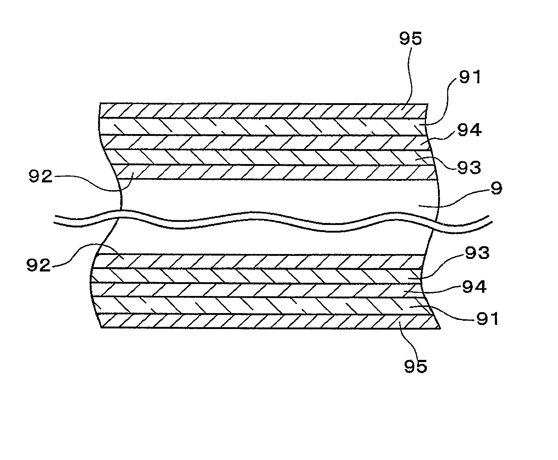
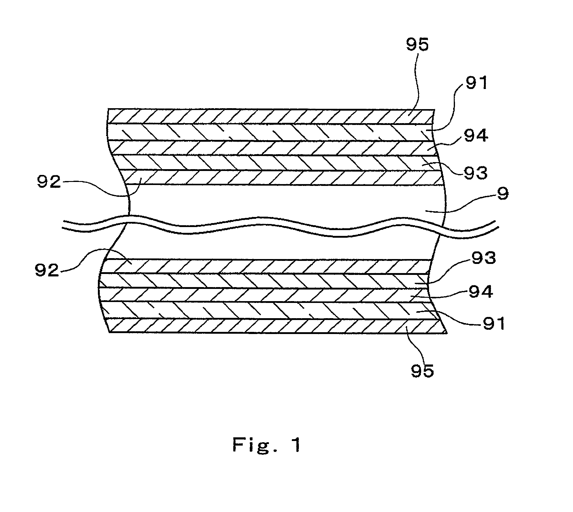
[0025] Preferred embodiments of this invention are described as follows. First of all, a magnetic recording disk as a preferred embodiment is described. It is shown in FIG. 1. The magnetic recording disk shown in FIG. 1 comprises a disk-shaped substrate 9, a magnetic recording layer 91 prepared on the substrate 9, and an anisotropy-allowing layer 92 prepared between the substrate 9 and the magnetic recording layer 91. The anisotropy-allowing layer 92 is to allow the magnetic anisotropy to the magnetic recording layer 91.

[0026] The substrate 9 is made of glass, which can be, for example, N5 of HOYA Corporation in Japan. The anisotropy-allowing layer 92, which is initially prepared on the substrate 9, characterizes this magnetic recording disk. An underlying layer 93 is prepared on the anisotropy-allowing layer 92. An intermediate layer 94 is prepared on the underlying layer 93. The magnetic recording layer 91 is prepared on the intermediate layer 94. An overcoat 95 is prepared on the...


PUM

PropertyMeasurementUnit
pressureaaaaaaaaaa
pressureaaaaaaaaaa
magneticaaaaaaaaaa

Abstract

This invention presents a magnetic recording disk where an anisotropy-allowing layer to allow magnetic anisotropy to a magnetic recording layer is provided between a substrate and the magnetic recording layer. This invention also presents a magnetic-recording-disk manufacturing method comprising a step to prepare an anisotropy-allowing layer to allow magnetic anisotropy to a magnetic recording layer, prior to a step to prepare the magnetic recording layer. This invention also presents a magnetic-recording-disk manufacturing system comprising an anisotropy-allowing-layer preparation chamber, in which an anisotropy-allowing layer to allow magnetic anisotropy to a magnetic recording layer is prepared on a substrate, prior to preparation of the magnetic recording layer. In this invention, the anisotropy-allowing layer is made of; nitride of niobium, tantalum, niobium alloy or tantalum alloy, or nitride-including niobium, tantalum, niobium alloy or tantalum alloy.

Description

BACKGROUND OF THE INVENTION[0001] 1. Field of the Invention[0002] This invention relates to magnetic recording disks widely used as storage media in computers, such as hard disks. This invention also relates to manufacture of such magnetic recording disks.[0003] 2. Description of the Related Art[0004] Magnetic recording disks such as hard disks and flexible disks are widely used as storage media in computers. Magnetic recording disks have a basic structure where a magnetic recording layer is provided on a disk-shaped substrate.[0005] Manufacture of a magnetic recording disk is described as follows, taking a hard disk as an example. Conventionally, a substrate made of aluminum is employed in manufacturing a hard disk. A NiP (nickel phosphide) film is deposited on the aluminum-made substrate. On the NiP film, such a film as CoCr film is deposited as an underling layer. On the underlying layer, such a film as CoCrTa film is deposited as a magnetic film for the magnetic recording layer....

Claims


Application Information

Patent Timeline
Patent Type & Authority Applications(United States)
IPC IPC(8): C22C27/02C23C14/06C23C14/34C23C14/58G11B5/64G11B5/65G11B5/73G11B5/738G11B5/84G11B5/851
CPCG11B5/7325G11B5/8404G11B5/7368
Inventor SHIBAMOTO, MASAHIROFURUKAWA, SINJIENDOH, TETSUYASAKAI, MIHOWATANABE, NAOKI
Owner CANON ANELVA CORP
Learn More