
Optical recording medium

Inactive Publication Date: 2002-09-12
SONY CORP
View PDF0 Cites 1 Cited by
  • Summary
  • Abstract
  • Description
  • Claims
  • Application Information

AI Technical Summary

Benefits of technology

[0012] In the course of accessing a track provided on this optical recording medium, the reading laser beam is applied to the detection pattern, generating a signal, as the light spot of the reading laser beam moves across the region where no grooves are made. The signal is used to count tracks, making it possible to access the track at high speed as is desired.
[0018] With the method of manufacturing a master disk, it is possible to easily form an latent image corresponding to a detection pattern, to a particular depth in a part corresponding to a pit pattern and to a different depth in the other part of the photosensitive layer.
[0020] With this method of manufacturing a master disk, it is possible to easily form an latent image corresponding to a detection pattern, which has a particular width in a part corresponding to a pit pattern and a different width in the other part of the photosensitive layer.

Problems solved by technology

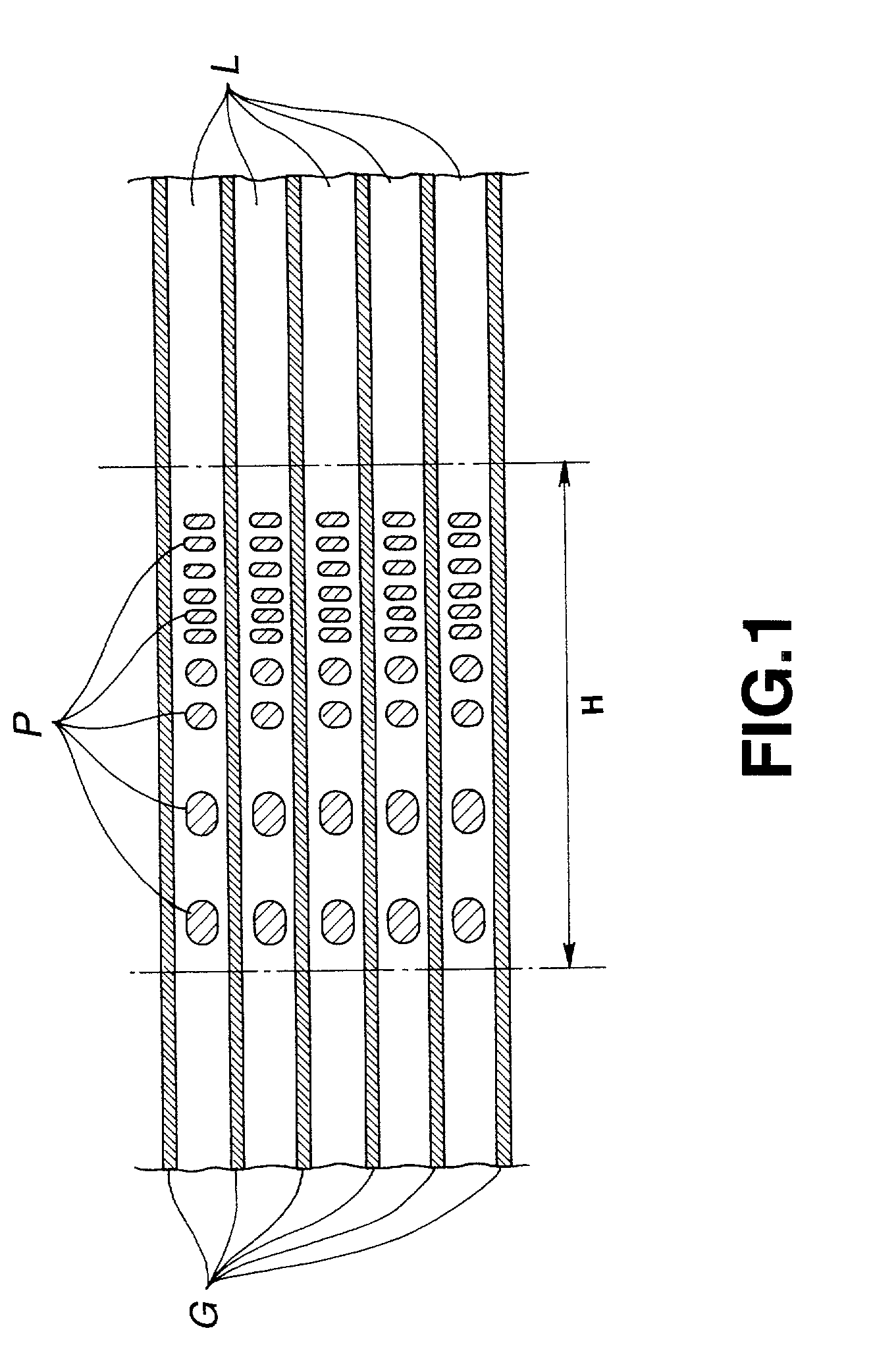
If the track pitch is decreased on the magneto-optical disk of the type mentioned above, however, it will be difficult to form pits for the management information between the adjacent grooves.
If the tack pitch is decreased, the two laser beam will interfere with each other, inevitably irradiating the region between each pit and an adjacent groove.
Consequently, desirable latent images may not be formed in some cases.
Magneto-optical disks made by the use of such a master disk have but a low reproducing modulation factor of pits, and appropriate signals cannot be reproduced from these magneto-optical disks.
With a magneto-optical disk of the discontinuous groove type, however, it is difficult to access the desired track at high speed.
As a consequence, the number of tracks the light spot has crossed may not be correctly counted in some cases.

Method used


Image

  • Optical recording medium
  • Optical recording medium
  • Optical recording medium

Examples


embodiment

[0062] (Embodiment Wherein M and S Parts Have Different Depths)

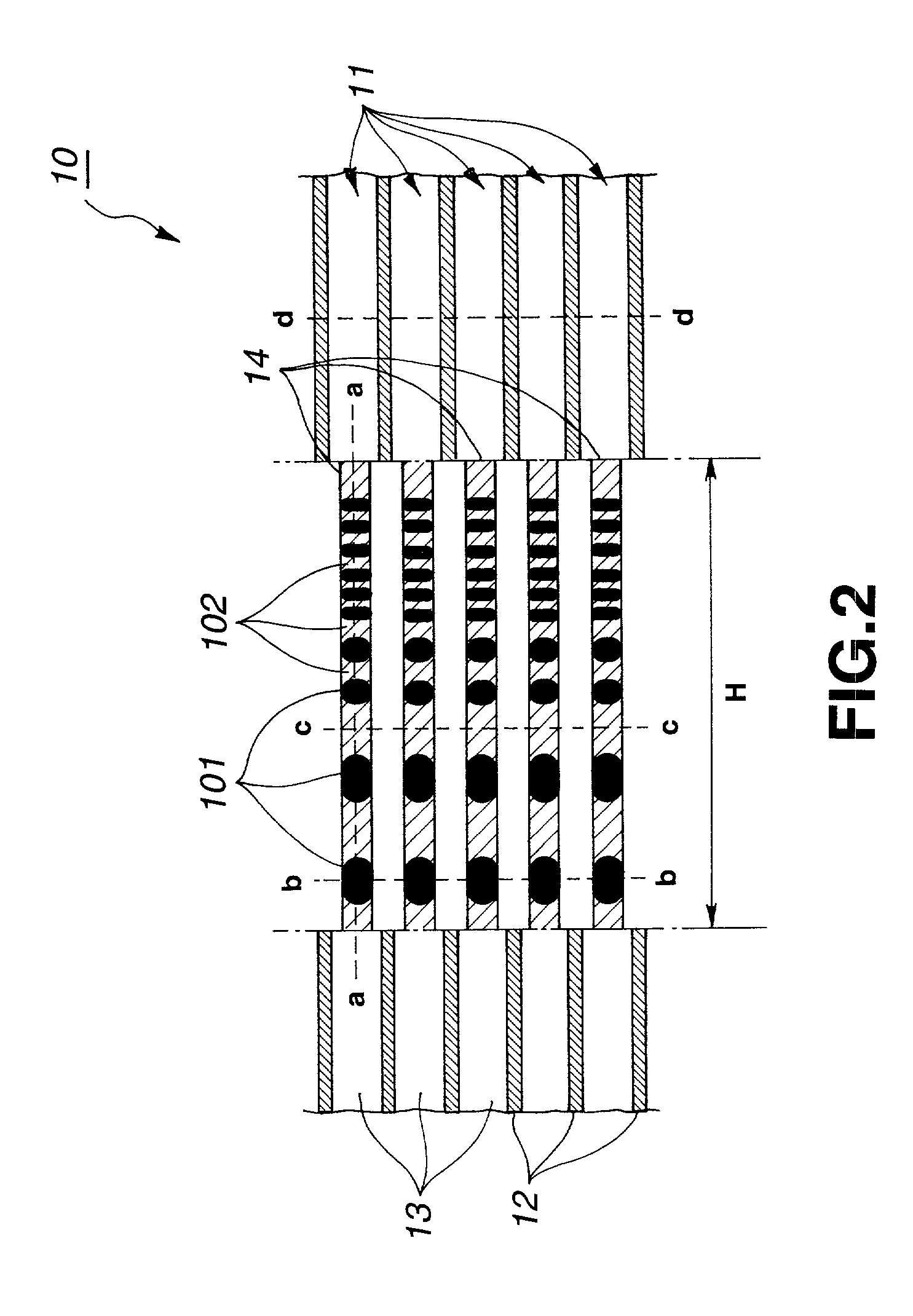
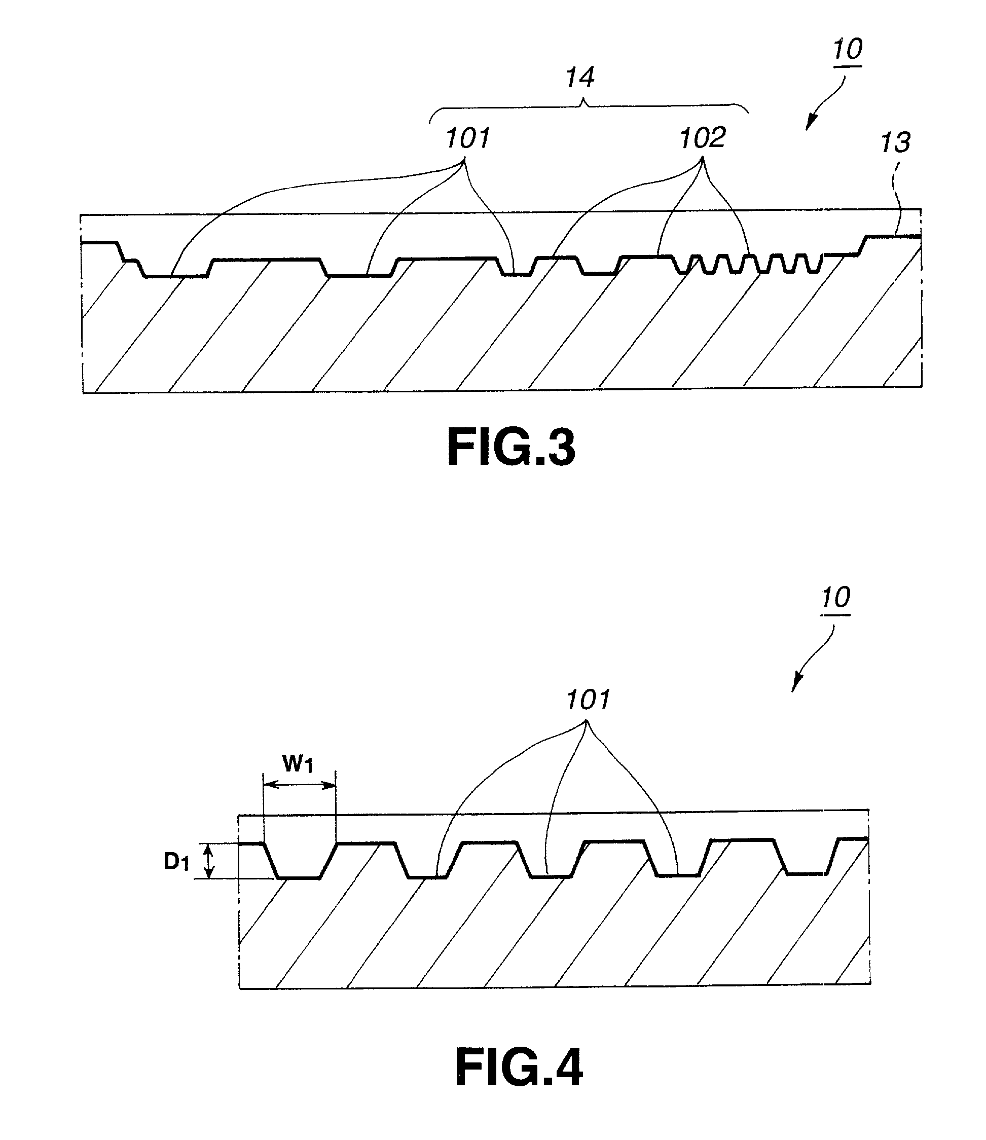
[0063] FIG. 2 to 6 shows a magneto-optical disk according to the present invention. In this embodiment, the M part 101 and the S part 102 differ in depth, imparting to the pit pattern a reproducing modulation factor that can be read. FIG. 2 is a magnified view of a part of the recording area of a magneto-optical disk 10 according to this embodiment. FIG. 3 is a sectional view taken along line a-a in FIG. 2; FIG. 4 is a sectional view taken along line b-b in FIG. 2; FIG. 5 is a sectional view taken along line c-c in FIG. 2; and FIG. 6 is a sectional view taken along line d-d in FIG. 2.

[0064] The magneto-optical disk 10 shown in FIGS. 2 to 6 has recording tracks 11 and grooves 12 that extend along the recording tracks 11. Each land 13 provided between two adjacent grooves 12 is used as a signal-recording region, in which signals will be recorded by means of magneto-optical recording.

[0065] On the magneto-optical disk 10, t...


PUM


Abstract

A magneto-optical disk 10 having recording tracks 11 are formed along concentric grooves 12 or a spiral groove 12. A non-groove region where no grooves 12 are made is provided in a middle part of each recording track 11. In the non-groove region there is formed a pit pattern representing information about the recording track 11. A track-counting U-groove 14 is formed in the non-groove region, for detecting that the light spot of a reading laser beam has moved across the recording track 11. With the disk thus structured, it is possible to record information at high density and to access a desired recording track at high speed.

Description

TECHNICAL FIELD[0001] The present invention relates to an optical recording medium on which information about recording tracks is recorded in the form of a bit pattern, an optical recording medium substrate for use in the optical recording medium, a method of manufacturing a master disk for use in manufacturing the optical recording medium, and a method of accessing tracks provided on the optical recording medium.BACKGROUND ART[0002] In recent years, disk recording / reproducing systems, each being small and having a large storage capacity and a high access speed, have come into use in increasing numbers. In these systems that optically record and reproduce data, magneto-optical disk system is reliable and can repeatedly record data on the recording medium and erase data therefrom. The magneto-optical disk system is therefore widely used.[0003] Used as a recording medium in the magneto-optical disk system is a magneto-optical disk. The magneto-optical disk in common use has concentric...

Claims


Application Information

Patent Timeline
IPC IPC(8): G11B7/007G11B7/013G11B7/085G11B7/24047G11B7/24091G11B7/26G11B11/10G11B11/105
CPCG11B7/007G11B7/00718G11B7/00745G11B7/08541G11B7/24085G11B7/261G11B11/10563G11B11/10565Y10T428/21G11B7/24047G11B2220/2525
Inventor TAKEMOTO, HIROYUKITAKEUCHI, ATSUSHIFUKUSHIMA, YOSHIHITOITOH, KENICHIMORIBE, MINEONUMATA, TAKEHIKO
Owner SONY CORP
Learn More