
Method and device for assembling optical components or an optical component and a substrate

a technology of optical components and substrates, applied in the direction of instruments, cladded optical fibres, optics, etc., can solve the problems of inability to generally apply the procedure to the production of two random optical components, deformation of contact surfaces, and inability to ensure the perpendicularity of the interface with the fibre axis in this procedure, etc., to achieve good temperature control, increase the adhesion, and reduce the effect of contacting surface deformation

Inactive Publication Date: 2002-08-29
ANDROMIS
View PDF9 Cites 23 Cited by
  • Summary
  • Abstract
  • Description
  • Claims
  • Application Information

AI Technical Summary

Benefits of technology

[0031] The first object of the invention is a process for assembling an optical component and a substrate, which makes it possible to avoid the disadvantages described hereinbefore.

Problems solved by technology

Consequently, this procedure cannot generally be applied to the production of an assembly of two random optical components.
In general terms, all these procedures lead to a deformation of the contacting surfaces by heating.
Moreover, in general, the optical fibres are prepared beforehand by cleaving, but the perpendicularity of the interface with respect to the fibre axis is not guaranteed in this procedure.
However, bonding is chemically sensitive to certain solvents and leads to a poor mechanical strength for small surfaces.
It also requires the introduction of a material (the adhesive), which reduces the optical quality of the path which can be followed by a beam.
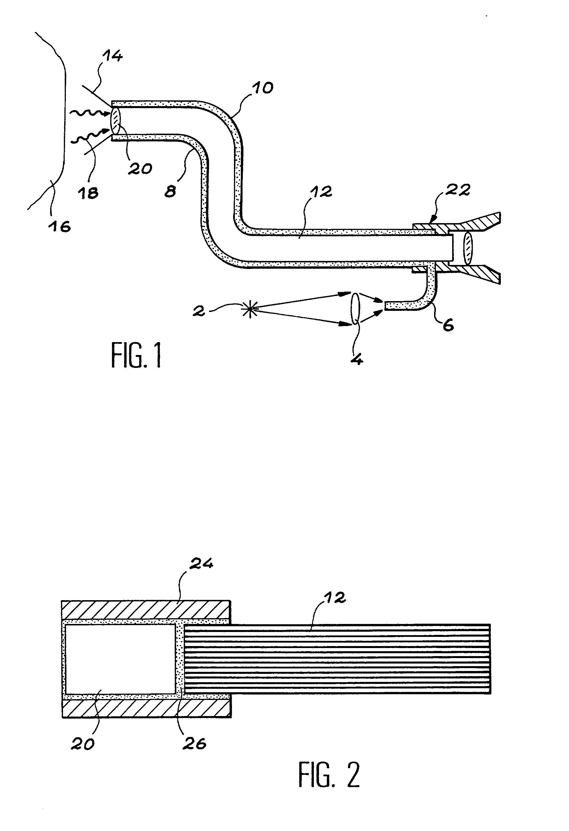
This procedure gives good results, but has the disadvantage of requiring difficult manipulation, of reducing the optical quality by introducing a supplementary medium 26 between the lens and the multicore fibre and of making the endoscope very vulnerable to the necessary heating-based sterilization stages.
Moreover, bonding takes place blind in the tube 24 and without any accurate control.
In general terms, the assembly or splicing of two optical components or an optical component and a substrate by bonding also suffers from a certain fragility and is not compatible with high or very high temperature uses, particularly when a sterilization is necessary.
The procedure described in this document does not solve the optical problems, i.e. the optical deterioration and disturbance to the beam when the latter has to traverse the glass connection.
The material adopted in said document for the weld (glass paste) is difficult to dose due to the evaporation of the binder, which considerably modifies the volume thereof.
The paste can also undergo chemical deteriorations making it inappropriate for use in optics.
Moreover, the homogenization necessary for reducing diffusion involves a temperature rise up to 1000.degree. C., which is unacceptable when certain optical components have to be contacted or welded to one another.
Finally, the use of glasses melting at low temperatures is not necessarily an advantage if their optical properties (refractive index) and thermal properties (expansion) are too different from those of the optical elements.
Finally, for the implementation described in said document (plunging the end of a fibre in a glass bath) does not make it possible to carry out a precise check on the deposited glass quantity, or on the alignment of the elements to be welded prior to the melting of the layer.
the stressing of a fibre, which can lead to refractive index variations, thereby disturbing the propagation of the signal,
Thus, the connection described in this document is inappropriate for producing an imaging device, particularly an endoscope.
Finally, the procedure adopted in this document does not make it possible to precisely check the deposited glass quantity or the alignment of the elements to be welded.
In addition, none of the procedures described hereinbefore is appropriate for producing assemblies of very different materials, e.g. an optical component and a shape memory, plastic, semiconductor or metal substrate.
The only known method making it possible to produce such assemblies is that of bonding, which suffers from the disadvantages referred to hereinbefore (lack of stability of certain solvents, poor mechanical strengths for small surfaces, introduction of a material (the adhesive) which disturbs the optical beams or reduces the optical quality of the path to be followed by a beam).
The known methods also do not permit the effecting of a precise adjustment of the surfaces to be contacted.
Finally, in the case of a metal-glass weld, conventional welding methods do not make it possible to eliminate deformations of the glass.

Method used


Image

  • Method and device for assembling optical components or an optical component and a substrate
  • Method and device for assembling optical components or an optical component and a substrate
  • Method and device for assembling optical components or an optical component and a substrate

Examples


Embodiment Construction

[0031] The first object of the invention is a process for assembling an optical component and a substrate, which makes it possible to avoid the disadvantages described hereinbefore.

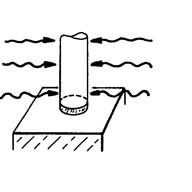
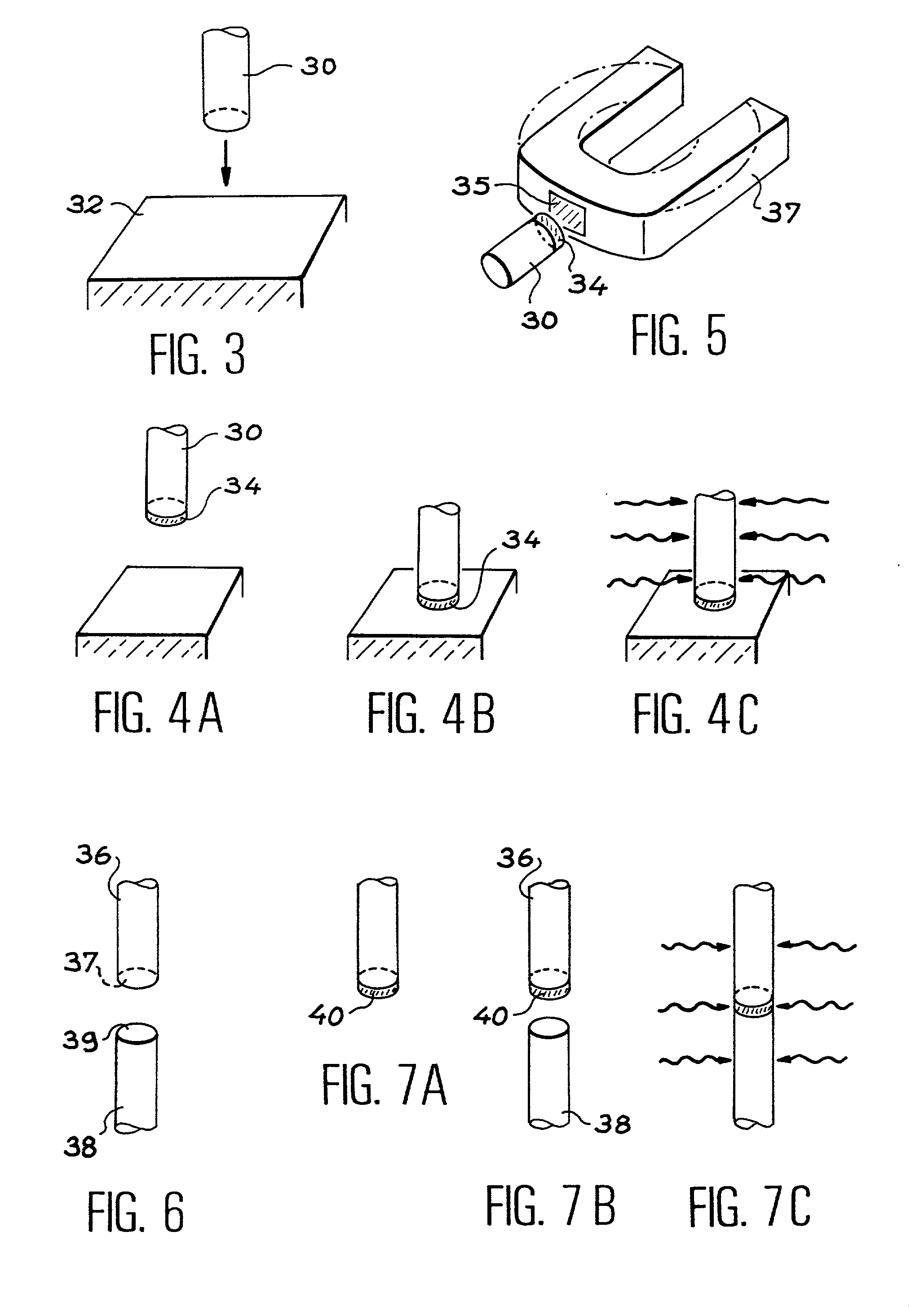
[0032] The invention firstly relates to a process for the assembly of an optical component with a substrate comprising:

[0033] a first stage of depositing a glass layer on at least one of the two faces or surfaces to be contacted,

[0034] a second stage of contacting the two faces or surfaces,

[0035] a third stage of heating the glass, leading to a weld between the optical component and the substrate.

[0036] The invention also relates to a process for the assembly of two optical components making it possible to avoid the disadvantages referred to hereinafter and which can in particular be applied to the implementation of imaging devices, e.g. endoscopes.

[0037] The invention therefore also relates to a process for the assembly of a first and a second optical components comprising:

[0038] a first stage of deposit...


PUM

PropertyMeasurementUnit
distanceaaaaaaaaaa
distanceaaaaaaaaaa
glass transition pointaaaaaaaaaa

Abstract

The invention relates to an assembly of an optical component (30) and a substrate (32) comprising: the optical component, the substrate, a glass layer (34) located at the interface between the optical component and the substrate. The invention also relates to an assembly between two optical components, which is particularly appropriate for use in the field of imaging, especially in endoscopy.

Description

TECHNICAL FIELD AND PRIOR ART[0001] The invention relates to the assembly or splicing between two optical components, particularly an optical fibre and another optical component, whereby the latter can e.g. be another optical fibre (particularly a multicore fibre) or a lens or microlens (particularly a graded-index or GRIN lens). The optical fibre can also be a multicore fibre. Another example of an optical element which can be assembled or spliced with the aid of the invention is a lens-prism assembly. The invention also relates to the assembly of an optical component and a substrate, e.g. a semiconductor or metal substrate. The component can e.g. be an optical fibre or a lens.[0002] The article by K. Kinoshita entitled "End preparation and fusion splicing of an optical fiber array with CO.sub.2 laser" published in Applied Optics, vol. 18, No. 19, pp 3256-3260, 1979 describes the fusion of optical fibres with the aid of a CO.sub.2 laser. The article by K. Egashira entitled "Analysi...

Claims


Application Information

Patent Timeline
Patent Type & Authority Applications(United States)
IPC IPC(8): C03C27/02C03C27/04C03C27/06G02B6/255G02B6/32G02B6/42
CPCC03C27/044C03C27/06G02B6/02042G02B6/2551G02B6/32
Inventor CONDE, RAMIRODEPEURSINGE, CHRISTIAN
Owner ANDROMIS
Learn More