
Multi-phasic microphotodetector retinal implant with variable voltage and current capability and apparatus for insertion

a multi-phasic, retinal implant technology, applied in the direction of radiation control devices, artificial respiration, therapy, etc., can solve the problems of preventing an blocking the discrete ion migration between the photoreceptor and inner retinal layer, and unable to achieve acceptable image resolution capability, etc., to achieve greater amplitude

Inactive Publication Date: 2002-07-25
OPTOBIONICS
View PDF0 Cites 27 Cited by
  • Summary
  • Abstract
  • Description
  • Claims
  • Application Information

AI Technical Summary

Benefits of technology

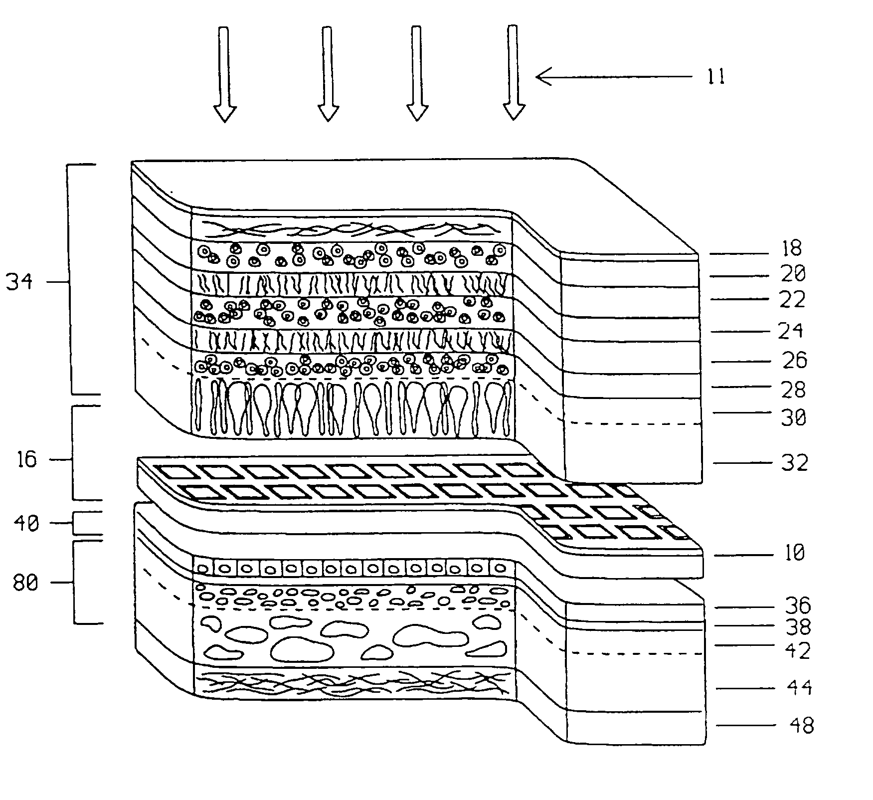
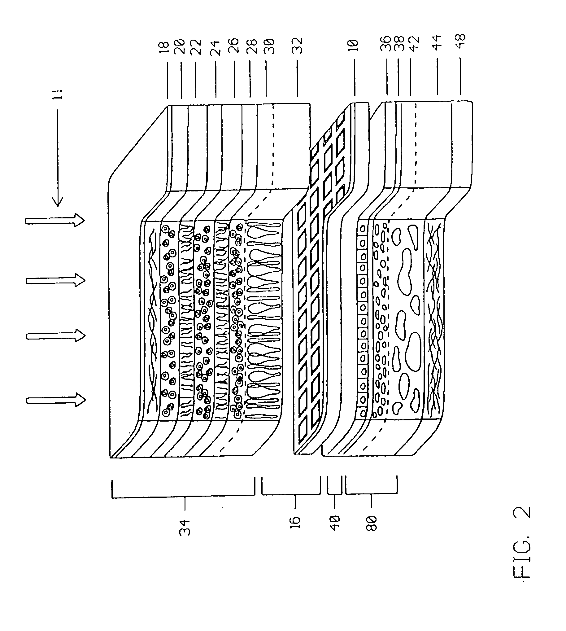
[0057] Although other electrode materials may be used, an advantage of the preferred iridium / iridium oxide electrode of this invention is that it supports better DC ionic flow into tissue in addition to having a higher capacitive effect than is possible with other electrode materials such as platinum. This results in lower work function for the VGMMRI 10 and thus the VGMMRI operates with lower electrode potentials. The lower electrode potentials result in better low light performance and lessen potential electrolysis damage to ocular tissues. Secondly, the larger capacitive effect of the preferred iridium / iridium electrode of the VGMMRI 10 provides a passive charge balance effect to the tissues during capacitive discharge of the electrode during the moments when light is absent.

Problems solved by technology

The success of this device is unlikely because it must duplicate the complex frequency modulated neural signals of a nerve fiber layer which runs in a general radial course with overlapping fibers from different portions of the retina.
However, because this device has no discrete surface structure to restrict the directional flow of the charges, lateral migration and diffusion of charges would occur thereby preventing an acceptable image resolution capability.
Placement of the device between the sclera and choroid would also result in blockage of discrete ion migration to the photoreceptor and inner retinal layers.
As the device would be inserted into or through the highly vascular choroid of the posterior pole, subchoroidal, intraretinal and intraorbital hemorrhage would likely result along with disruption of blood flow to the posterior pole.
Even with fenestrations of various geometries, permeation of oxygen and biological substances is not optimal.
However, like the SEMCP device, the ISEMCP depends upon light from the visual environment to power it, and so the ability of this device to function in low light environments is limited.
The ISEMCP also does not provide a way to address localized variations in the sensitivity to electrical stimulation of surviving retinal tissue.

Method used


Image

  • Multi-phasic microphotodetector retinal implant with variable voltage and current capability and apparatus for insertion
  • Multi-phasic microphotodetector retinal implant with variable voltage and current capability and apparatus for insertion
  • Multi-phasic microphotodetector retinal implant with variable voltage and current capability and apparatus for insertion

Examples


Embodiment Construction

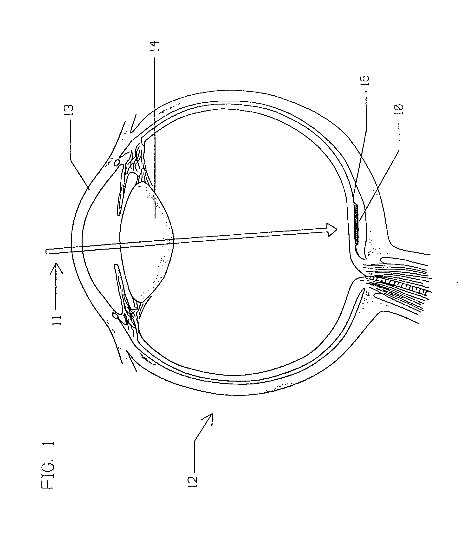
[0025] As described in further detail below, the present invention relates to a retinal implant that can vary its stimulation voltage polarity and also produce higher stimulation voltages and currents to the retina compared to retinal implants of the prior art. This higher and adjustable stimulation voltage and current allow for higher voltage and / or current stimulation thresholds that may be required to stimulate severely damaged retinal tissue. Although a preferred embodiment of the retinal implant disclosed below may be used on its own, without the need for any special stimulation apparatus positioned outside of the eye, in another embodiment the implant stimulation voltages and currents of the present invention are adaptable to the specific needs of a retina by the addition of regulated amounts of different wavelengths of projected images and background illumination light provided by a headset device that projects the different wavelengths into the eye. The use of this headset a...


PUM


Abstract

A visible and infrared light powered retinal implant is disclosed that is implanted into the subretinal space for electrically inducing formed vision in the eye. The retinal implant includes a stacked microphotodetector arrangement having an image sensing pixel layer and a voltage and current gain adjustment layer for providing variable voltage and current gain to the implant so as to obtain better low light implant performance than the prior art, and to compensate for high retinal stimulation thresholds present in some retinal diseases. A first light filter is positioned on one of the microphotodetectors in each of the image sensing pixels of the implant, and a second light filter is positioned on the other of the microphotodetectors in the image sensing pixel of the implant, each of the microphotodetectors of the pixel to respond to a different wavelength of light to produce a sensation of darkness utilizing the first wavelength, and a sensation of light using the second wavelength, and a third light filter is positioned on a portion of the voltage and current gain adjustment layer that is exposed to light, to allow adjustment of the implant voltage and current gain of the device by use of a third wavelength of light.

Description

[0001] The present invention relates to medical products that are implanted into the eye that can restore a degree of vision to persons with vision loss caused by certain retinal diseases.[0002] A variety of retinal diseases cause vision loss by destruction of the outer retinal vasculature and certain outer and inner retinal layers of the eye. The inner retina is also known as the neuroretina. The outer retinal vasculature is comprised of the choroid and choriocapillaris, and the outer retinal layers are comprised of Bruch's membrane and retinal pigment epithelium. The outer portion of the inner retinal layer that is affected is the photoreceptor layer. Variable sparing of other inner retinal layers, however, may occur. These spared inner retinal layers include the layers of the outer nuclei, outer plexiform, inner nuclei, inner plexiform, amacrine cells, ganglion cells, and the nerve fibers. The sparing of these inner retinal layers allows electrical stimulation of one or more of t...

Claims


Application Information

Patent Timeline
Patent Type & Authority Applications(United States)
IPC IPC(8): A61F9/08A61F2/14A61N1/05A61N1/36H01L27/14H01L27/146H04N5/325
CPCA61F9/08A61N1/0543A61N1/36046A61N1/18B82Y5/00
Inventor CHOW, VINCENTCHOW, ALAN Y.
Owner OPTOBIONICS
Learn More