
Vehicle braking control method and apparatus

Inactive Publication Date: 2002-06-20
TOYOTA JIDOSHA KK
View PDF0 Cites 11 Cited by
  • Summary
  • Abstract
  • Description
  • Claims
  • Application Information

AI Technical Summary

Benefits of technology

[0009] According to the first aspect of the invention, if an abnormal state in which the control of the braking force in the controlled braking mode cannot be continued is predicted, the controlled braking mode is switched to the driver braking mode by the controller. However, before the switch from the controlled braking mode to the driver braking mode, the ratio of the braking force generated by the controller to the amount of braking operation of the driver is adjusted closer to the ratio set for the driver braking mode by the controller. Therefore, the braking control apparatus reliably prevents an occurrence where the ratio of the braking force generated by the valve to the amount of braking operation of the driver sharply falls at the time of switching from the controlled braking mode to the driver braking mode.
[0011] According to the second aspect of the invention, if an abnormal state in which the control of the braking force in the controlled braking mode cannot be continued is predicted, the ratio of the braking force generated by the valves to the amount of braking operation of the driver is adjusted closer to the ratio set for the driver braking mode by the controller. Therefore, if the controlled braking mode is switched to the driver braking mode upon occurrence of the abnormal state in which the control of the braking force in the controlled braking mode cannot be continued, the ratio of the braking force generated by the valves to the amount of braking operation of the driver is reliably prevented from sharply falling.
[0012] In the first and second aspects, the controller may adjust the ratio of the braking force generated by the valves to the amount of braking operation of the driver closer to the ratio set for the driver braking mode by reducing a ratio of the target amount of braking control to the amount of braking operation of the driver.
[0013] It is possible to easily and reliably adjust the ratio of the braking force generated by the valves to the amount of braking operation of the driver closer to the ratio set for the driver braking mode by adjusting the ratio of the braking force generated by the valves to the amount of braking operation of the driver closer to the ratio set for the driver braking mode by reducing the ratio of the target amount of braking control to the amount of braking operation of the driver. To the contrary, it is difficult to adjust the ratio of the braking force generated where the amount of braking operation caused by the driver serves as a basis for calculating the target amount of braking control, or a case where the braking force generated by the valves is reduced for correction.
[0015] The controller operates on electric energy supplied from the electric energy source and can predict an abnormality in the electric energy source. The ratio of the braking force generated by the valves to the amount of braking operation of the driver can be reliably adjusted by the controller closer to the ratio set for the driver braking mode even if the braking control mode is switched to the driver braking mode due to an abnormality in the electric energy source.

Problems solved by technology

Therefore, the conventional braking control apparatus as described above have the following problem.
Therefore, the ratio of the vehicle deceleration to the amount of driver's braking operation sharply reduces, thereby causing the driver to experience an uncomfortable feeling.
To the contrary, it is difficult to adjust the ratio of the braking force generated where the amount of braking operation caused by the driver serves as a basis for calculating the target amount of braking control, or a case where the braking force generated by the valves is reduced for correction.
Furthermore, the electric energy source may have a first electric energy source and a second electric energy source, and the controller may predict an abnormality in the electric energy source by detecting a dangerous condition of one of the first electric energy source and the second electric energy source losing a function thereof.

Method used


Image

  • Vehicle braking control method and apparatus
  • Vehicle braking control method and apparatus
  • Vehicle braking control method and apparatus

Examples


first embodiment

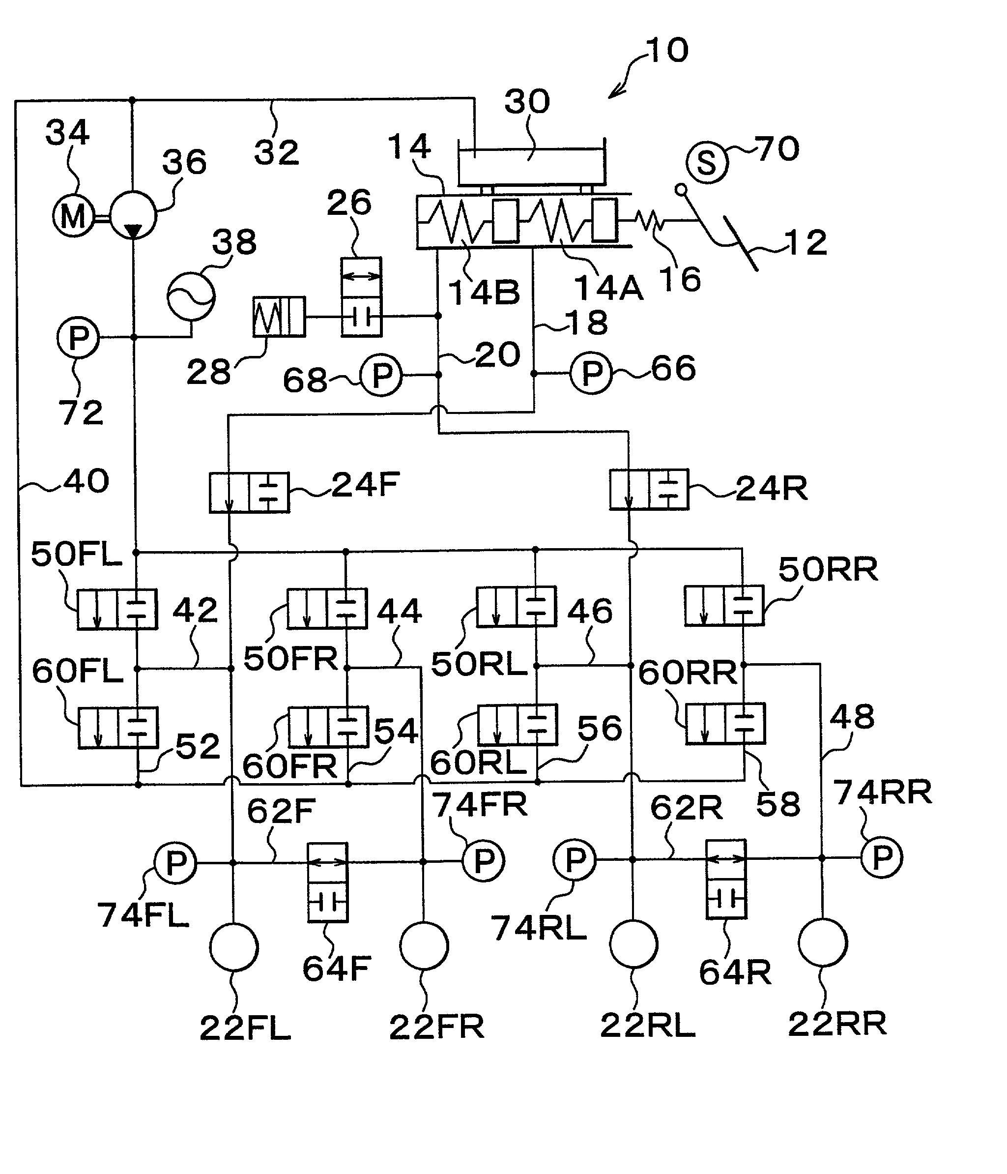
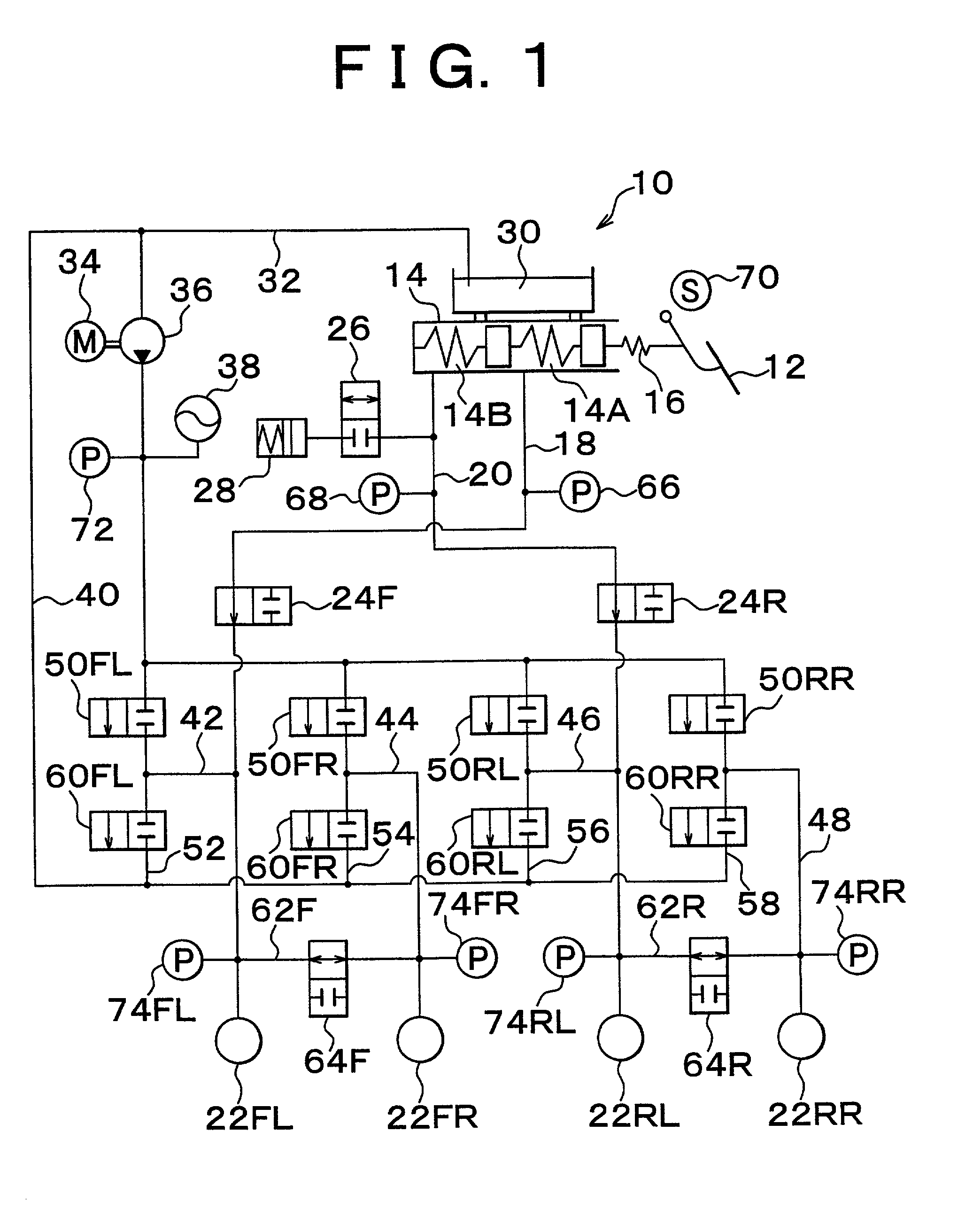
[0050] In the first embodiment shown in the figures, in particular, M in the correction factor M.sup.j is set to a / b where a and b are constants and satisfy 0<a<b<1, and j is incremented by "1" every time the state changes from a state where there is no braking request from the driver to a state where there is a braking request while the power source 82 is in the backup mode based on the subsidiary power source 86. Therefore, the corrected final target vehicle deceleration Gta is gradually decreased, so that the ratio of the wheel braking force to the amount of driver's braking operation is gradually made closer to the ratio set for the driver braking mode.

[0051] When j reaches a pre-set value Nc+1 (a predetermined positive integer), that is, when the correction factor M.sup.j becomes equal to a pre-set value, the brake apparatus 10 is switched from the braking control mode to the driver braking mode, that is, returned to a state where the braking pressure of each wheel is directly ...

second embodiment

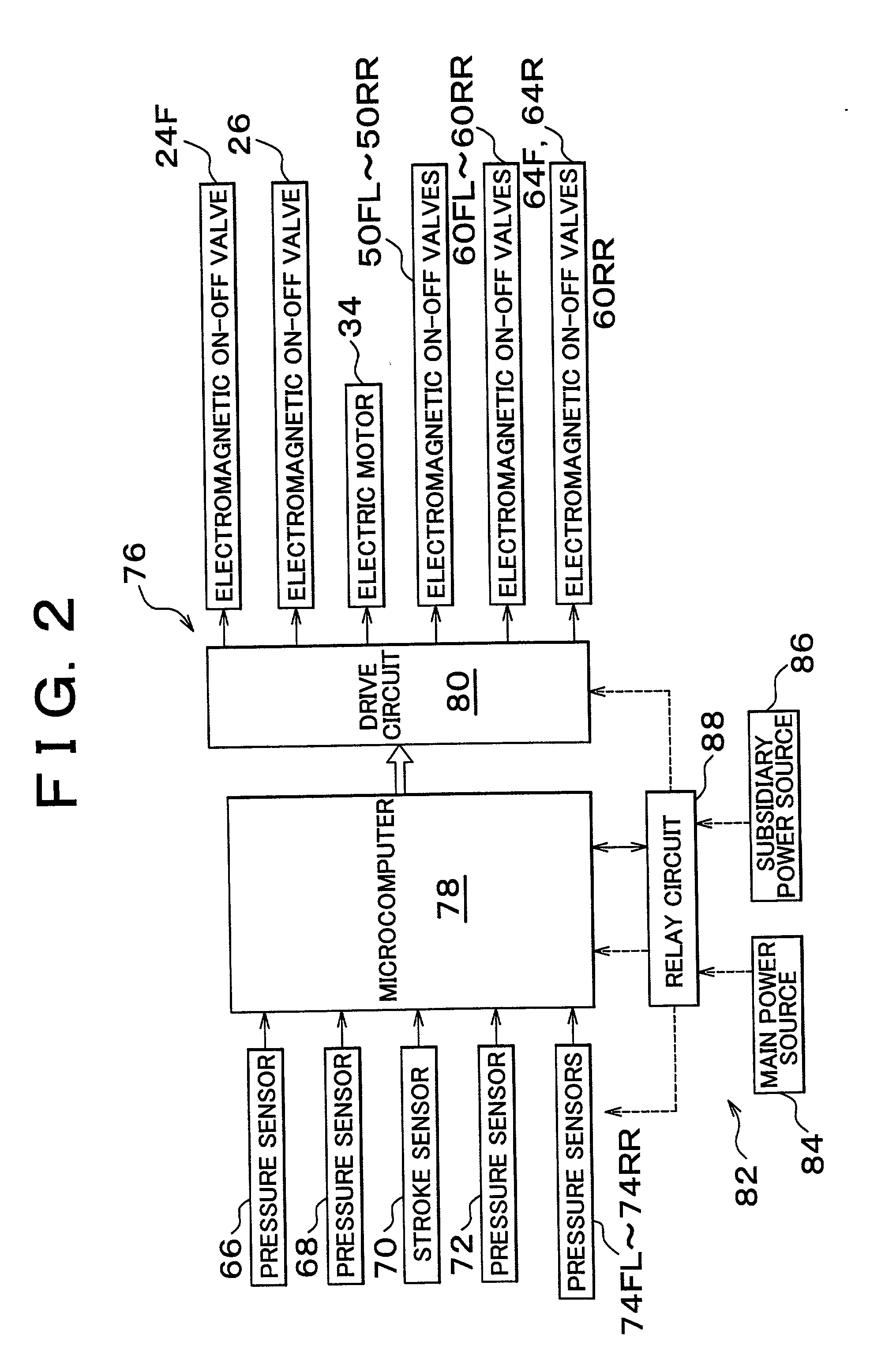
[0070] Furthermore, as illustrated in FIG. 9, in step S15 in the second embodiment, it is determined whether the voltage Ve of the power source 82 is less than a reference value Veh (positive constant). If the determination is negative (NO), that is, if it is determined that the voltage of the power source 82 has not dropped, the correction factor M is set to "1" in step S25 followed by step S90. Conversely, if the determination is affirmative (YES), that is, if it is determined that the voltage of the power source 82 has dropped, an alarm is outputted indicating that the brake apparatus 10 may enter a driver braking mode in step S35 followed by step S50.

[0071] In step S50, a determining process, such as in the first embodiment, is performed. If the determination is negative, that is, if it is determined that the change from the state where there is no braking request from a driver to the state where there is a braking request has not occurred, the process immediately proceeds to st...


PUM


Abstract

A method and apparatus control target deceleration of a vehicle in response to a master cylinder pressure and the like. A controlled braking mode in which the pressure in each wheel cylinder is controlled based on the target deceleration, and a driver braking mode in which the pressure in each wheel cylinder is directly controlled by a master cylinder. When an abnormality in the braking control is detected, the ratio of the wheel braking force to the amount of driver's braking operation is gradually adjusted closer to the ratio set for the driver braking mode.

Description

INCORPORATION BY REFERENCE[0001] The disclosure of Japanese Patent Application No. 2000-383668 filed on Dec. 18, 2000 including the specification, drawings and abstract is incorporated herein by reference in its entirety.[0002] 1. Field of Invention[0003] The invention relates to a braking control method and apparatus for a vehicle such as a motor vehicle or the like. More particularly, the invention relates to a braking control method and apparatus that controls the braking force based on the amount of braking operation performed on a brake operating member by an operating person.[0004] 2. Description of Related Art[0005] A conventionally known braking control apparatus for a vehicle such as a motor vehicle or the like is a braking control apparatus described in, for example, Japanese Patent Application Laid-Open No. 2000-25605, which is designed to operate in a braking control mode in which braking force generating means for each wheel is controlled by electric-type braking contro...

Claims


Application Information

Patent Timeline
IPC IPC(8): B60T8/40B60T8/96B60T8/17B60T13/74B60T17/22
CPCB60T8/4081B60T17/221B60T13/745B60T8/96B60T17/22
Inventor FUKASAWA, TSUKASA
Owner TOYOTA JIDOSHA KK
Learn More