Amorphous hard carbon film, mechanical parts and method for producing amorphous hard carbon film
a technology of hard carbon film and mechanical parts, applied in the field of protective effects, can solve the problem that the friction coefficient of conventional amorphous carbon film cannot be shown from the beginning, and achieve the effect of reducing the friction coefficient and decreasing the friction coefficien
- Summary
- Abstract
- Description
- Claims
- Application Information
AI Technical Summary
Benefits of technology
Problems solved by technology
Method used
Image
Examples
example 1
Addition of Oxygen
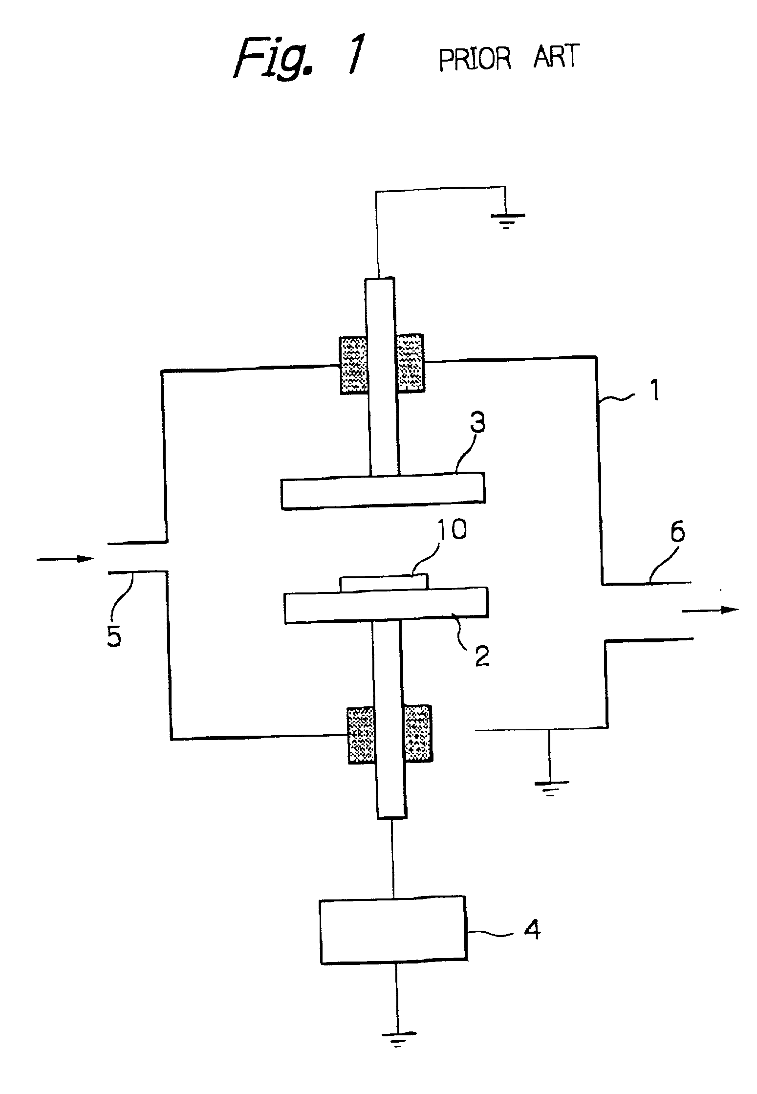
[0051] The substrate used was mirror-polished SKH 51. Amorphous hard carbon film was formed on the substrate by the RF plasma enhanced CVD method and its evaluation test was carried out. The RF plasma enhanced CVD method used for forming the film is schematically shown in FIG. 1.
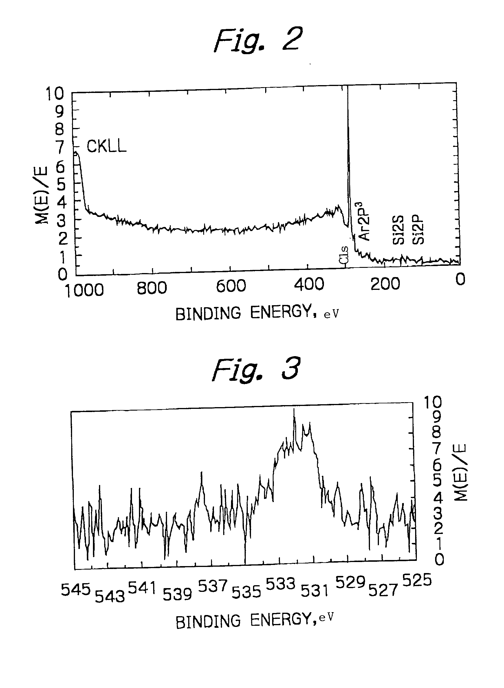
[0052] A pump (not shown) was connected to the evacuation port 6 of the vacuum chamber 1 and was operated to evacuate it to 5.2E-8 Pa or less. Ar gas was then introduced through the gas-inlet 5 and the pressure was controlled to 7.5E-5 Pa. High frequency power of 300W was applied through the RF power source 4 between the lower electrode 2 and the upper electrode 3 to generate plasma between those electrodes. The work piece (the substrate) 10 was placed on the lower electrode 2 and was cleaned by the Ar plasma for a predetermined time. The high-frequency power source was then turned off to stop the plasma discharge. The supply of Ar gas was terminated. Acethylene, tetramethylsilane and oxyge...
example 2
Use of Oxygen-Containing Compound
[0056] The film formation was carried out under the same conditions as in Example 1 except that tetraethoxysilane (TEOS, (Si(OC.sub.2H.sub.5).sub.4-) was used in place of oxygen. The partial pressure ratio of the gases was adjusted to C.sub.2H.sub.2:TMS:TEOS=8:1:1. The total pressure was adjusted to 5.25E-5 Pa. The XPS analysis indicated the formation of SiO.sub.2 in the film as in Example 1.
2 TABLE 2 No of Samples Film Thickness (.mu.m) Friction coefficient Example 1 1 0.05 Example 2 1 0.05 Comparative 1 0.2 Example 1
[0057] It is apparent from the comparison of the friction coefficient in Table 2 that it is high in the case where no oxide such as SiO.sub.2 is present in the film. In Examples 1 and 2, in which SiO.sub.2 is present in the film, the friction coefficient is 0.05 and hence low.
example 3
Piston Ring
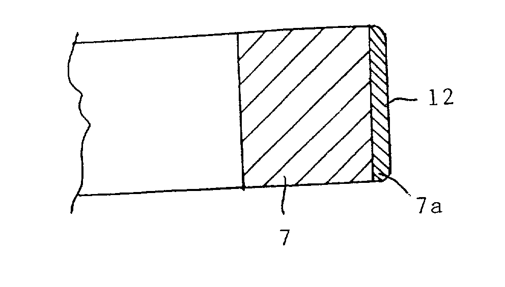
[0058] FIG. 4 shows an example of a piston ring, to which the present invention is applied. FIG. 5 also shows an example of a three piece type oil control piston ring, to which the present invention is applied. The amorphous hard carbon films 12 with the right hand down hatching is formed on the outer peripheral surfaces 7a and 10a, the inner peripheral surface 10b and the side surface 10c of the piston ring 7 and the rail 10 of the three piece type oil control piston ring. In addition, the amorphous hard carbon film 12 is also formed on the ear portion 4 of the spacer expander 13, where it is brought into contact with the rail 10. The amorphous hard carbon film 12 is formed by the plasma enhanced CVD method and contains the metal oxide as described above.
[0059] Piston rings 42 to be subjected to nitriding and cleaning in advance were placed on the electrode plates 44 electrically connected with the RF power source 44 shown in FIG. 8. A pump (not shown) connected to the e...
PUM
| Property | Measurement | Unit |
|---|---|---|
| thick | aaaaa | aaaaa |
| friction coefficient | aaaaa | aaaaa |
| temperature | aaaaa | aaaaa |
Abstract
Description
Claims
Application Information
 - R&D
- Intellectual Property
- Life Sciences
- Materials
- Tech Scout
- Unparalleled Data Quality
- Higher Quality Content
- 60% Fewer Hallucinations
Browse by: Latest US Patents, China's latest patents, Technical Efficacy Thesaurus, Application Domain, Technology Topic, Popular Technical Reports.
© 2025 PatSnap. All rights reserved.Legal|Privacy policy|Modern Slavery Act Transparency Statement|Sitemap|About US| Contact US: help@patsnap.com


