
Magnetic thin film and process for producing the same

Inactive Publication Date: 2002-02-14
TODA IND
View PDF0 Cites 6 Cited by
  • Summary
  • Abstract
  • Description
  • Claims
  • Application Information

AI Technical Summary

Problems solved by technology

However, magnetic thin films satisfying such requirements have not been obtained until now.
However, there is no magnetic film constituted by a ferromagnetic film in the form of a micro dot having a perpendicular magnetization component at a center portion thereof.

Method used


Image

  • Magnetic thin film and process for producing the same
  • Magnetic thin film and process for producing the same
  • Magnetic thin film and process for producing the same

Examples


example 1

[0062]

[0063] A 0.6 mm-thick Si single crystal substrate provided on the surface thereof with a thermal oxidation film was used as a substrate. After the substrate was sequentially washed with distilled water, 2-butanone and 2-propanol, a positive-type resist ZEP520-22 (tradename: produced by Nihon Zeon Co., Ltd.) was coated on the substrate using a spinner to form a resist film thereon. The thus coated resist film had a thickness of about 300 nm. The substrate coated with the resist film was then heat-treated at 180.degree. C. for 30 minutes to evaporate volatile components having a low molecular weight from the resist film.

[0064] Next, electron beam was irradiated on the resist film for patterning thereof. More specifically, the resist film was irradiated with electron beam using an electron-beam image forming apparatus "JBX-5000SF" (manufactured by JEOL LTD) in which LaB.sub.6 single crystal was used as an electron beam source, and the accelerated voltage was set to 50 kV. After ...

example 2

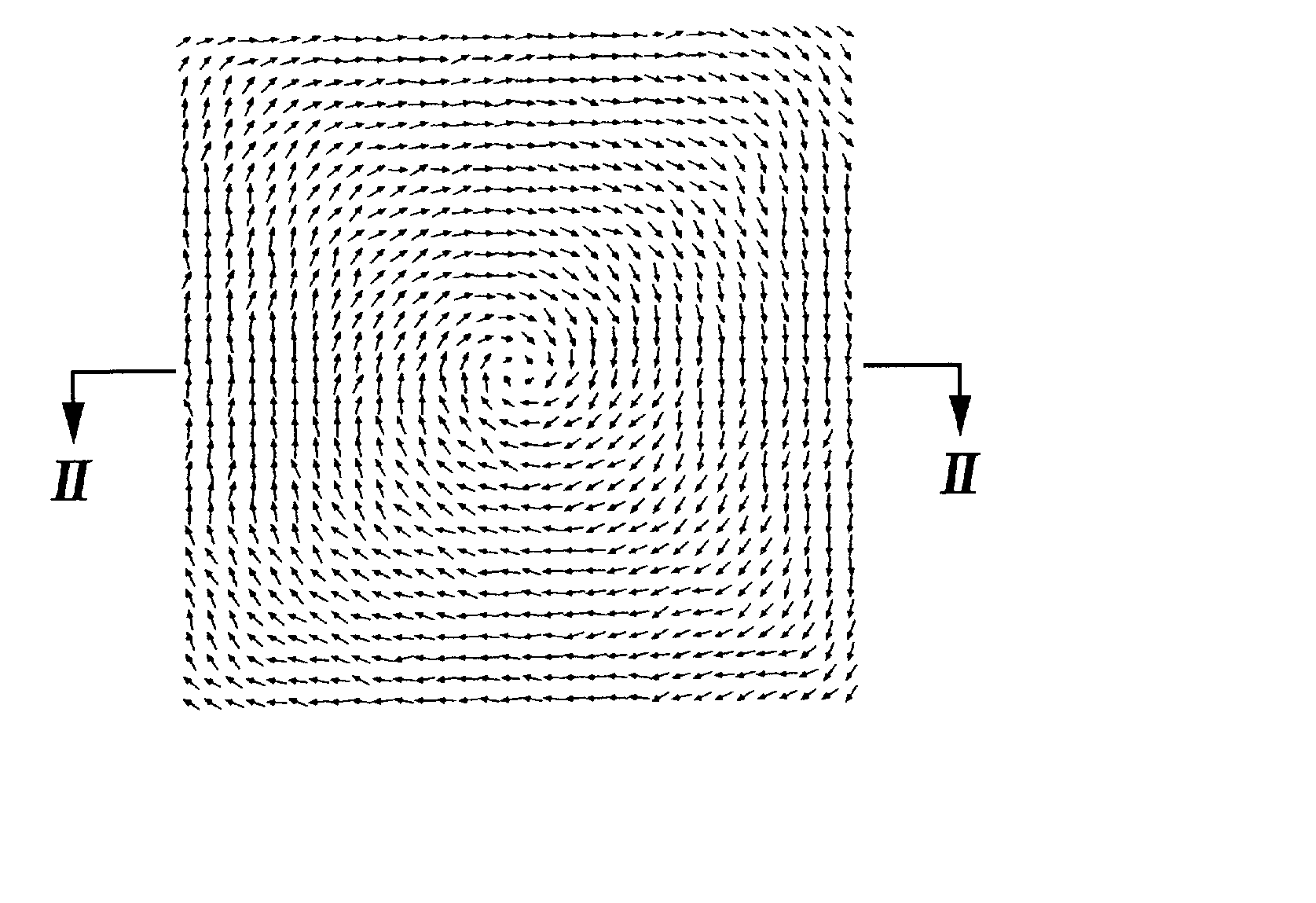
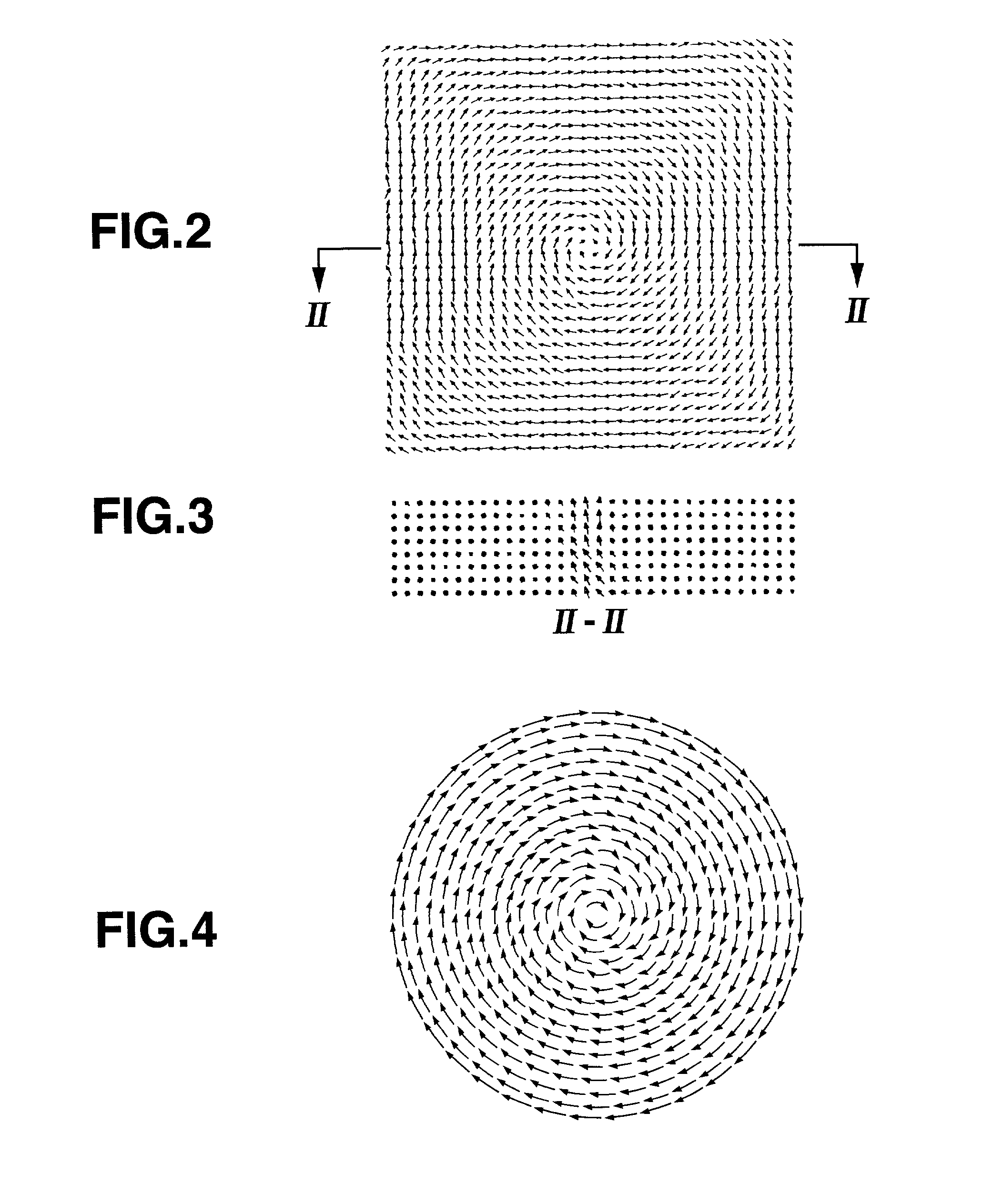
[0069] The same procedure as defined in Example 1 was conducted except that ten disc-shaped ferromagnetic films having different average diameters ranging from 0.1 to 1 .mu.m were formed on the substrate, thereby obtaining a magnetic thin film. Then, an external magnetic field of 1193.7 kA / m (15 kOe) was applied to the obtained magnetic thin films in the in-plane direction. The magnetic thin film was observed by a magnetic force microscope. FIG. 7 shows an MFM photograph of the magnetic thin film. Since a white or black spot was observed only at the center portion of each ferromagnetic film, it was confirmed that each ferromagnetic film had at the center thereof a perpendicular magnetization component oriented or magnetized in the up or down direction perpendicular to the surface thereof. Further, since each ferromagnetic film showed a uniform color tone except for the center thereof, it was confirmed that the circulating magnetic domain structure (vortex structure or spiral magneti...


PUM


Abstract

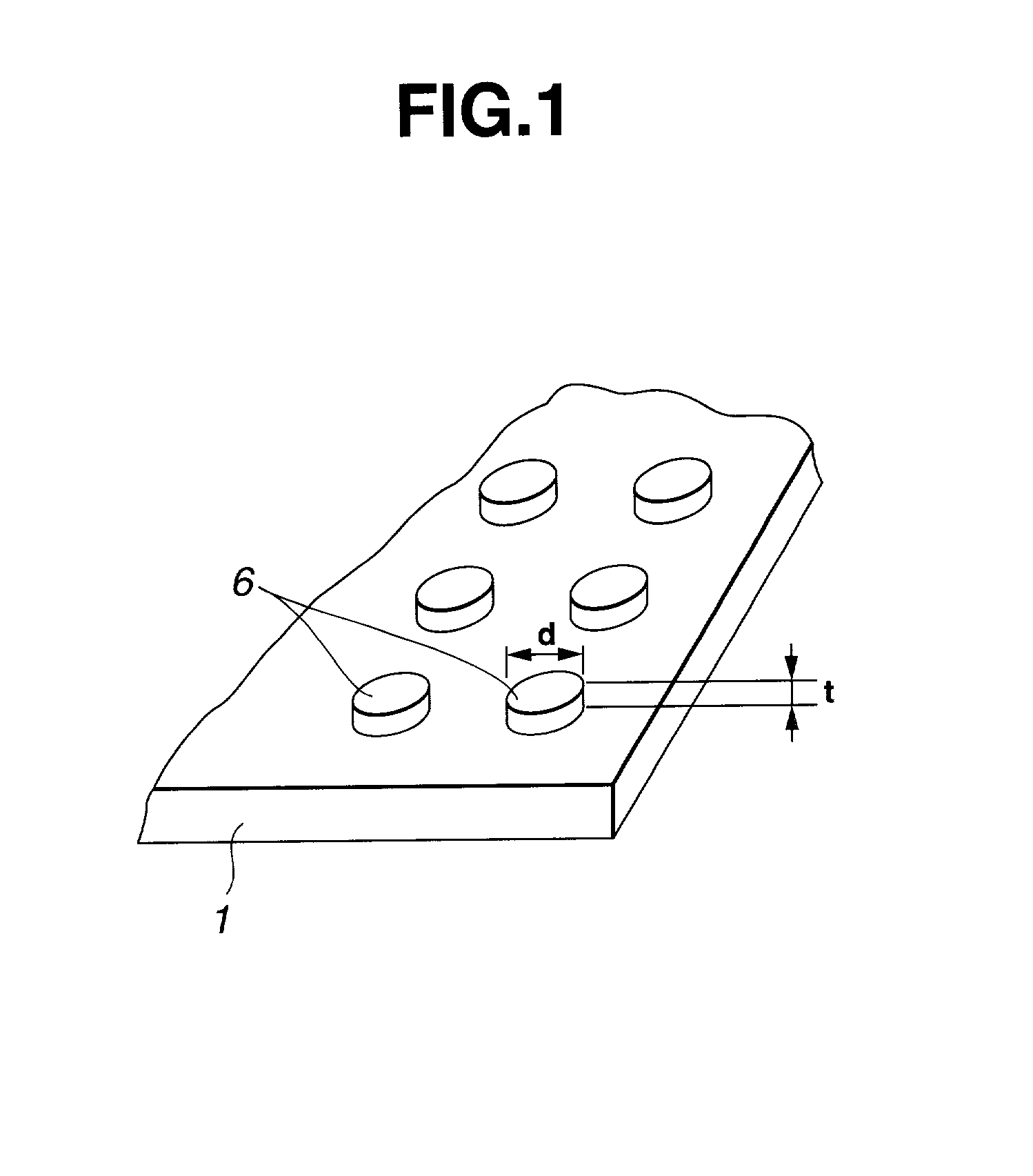
A magnetic thin film of the present invention comprises: a substrate; and a ferromagnetic film being formed on the substrate and having an average diameter of 0.1 to 10 mum, a thickness of 0.005 to 1.5 mum and a ratio of the thickness to the average diameter of not more than 0.5:1, wherein the ferromagnetic film having at a center portion thereof a perpendicular magnetization component, which is oriented or magnetized in the up or down direction perpendicular to the surface of the magnetic thin film.

Description

BACKGROUND OF THE INVENTION:[0001] The present invention relates to a magnetic thin film and a process for producing the magnetic thin film, and more particularly, to a magnetic thin film comprising a ferromagnetic film (micro dot) being formed on a substrate using micro-processing techniques and having a perpendicular magnetization component at a center portion thereof, and a process for producing such a magnetic thin film.[0002] At present, magnetic materials have been used in various applications. The magnetism of these magnetic materials is produced due to two kinds of electron spins, i.e., those oriented in up and down directions. By controlling the directions of the electron spins, the magnetic materials have been already put into practice in many applications, and are highly expected to further expand the application fields. Examples of such applications in which the magnetic materials have been already used, include longitudinally or perpendicularly magnetizable magnetic rec...

Claims


Application Information

Patent Timeline
IPC IPC(8): G11B5/64G11B5/73G11B5/84G11B5/855H01F1/00
CPCB82Y25/00G11B5/653G11B5/7315G11B5/84G11B5/855H01F1/009G11B5/739
Inventor SHINJO, TERUYA
Owner TODA IND
Learn More