Rake reception apparatus

a technology of rake and reception device, which is applied in the direction of electrical apparatus, digital transmission, synchronising arrangement, etc., can solve the problems of circuit scale and increase the power consumption of the reception device, and achieve the effect of reducing the circuit scale and reducing the power consumption

Inactive Publication Date: 2002-02-14
NEC CORP
View PDF10 Cites 7 Cited by
  • Summary
  • Abstract
  • Description
  • Claims
  • Application Information

AI Technical Summary

Benefits of technology

[0012] It is therefore an object of the present invention to overcome the above problem and provide a device which, while maintaining the function for tracking the phase jitter of the multipath propagation route, is able to reduce the circuit scale to lower the power consumption.

Problems solved by technology

Moreover, the phase control of the respective DLL circuits need to be performed in unison, as a result of which the circuit scale and the power consumption of the reception device are increased.

Method used


Image

  • Rake reception apparatus
  • Rake reception apparatus
  • Rake reception apparatus

Examples


Embodiment Construction

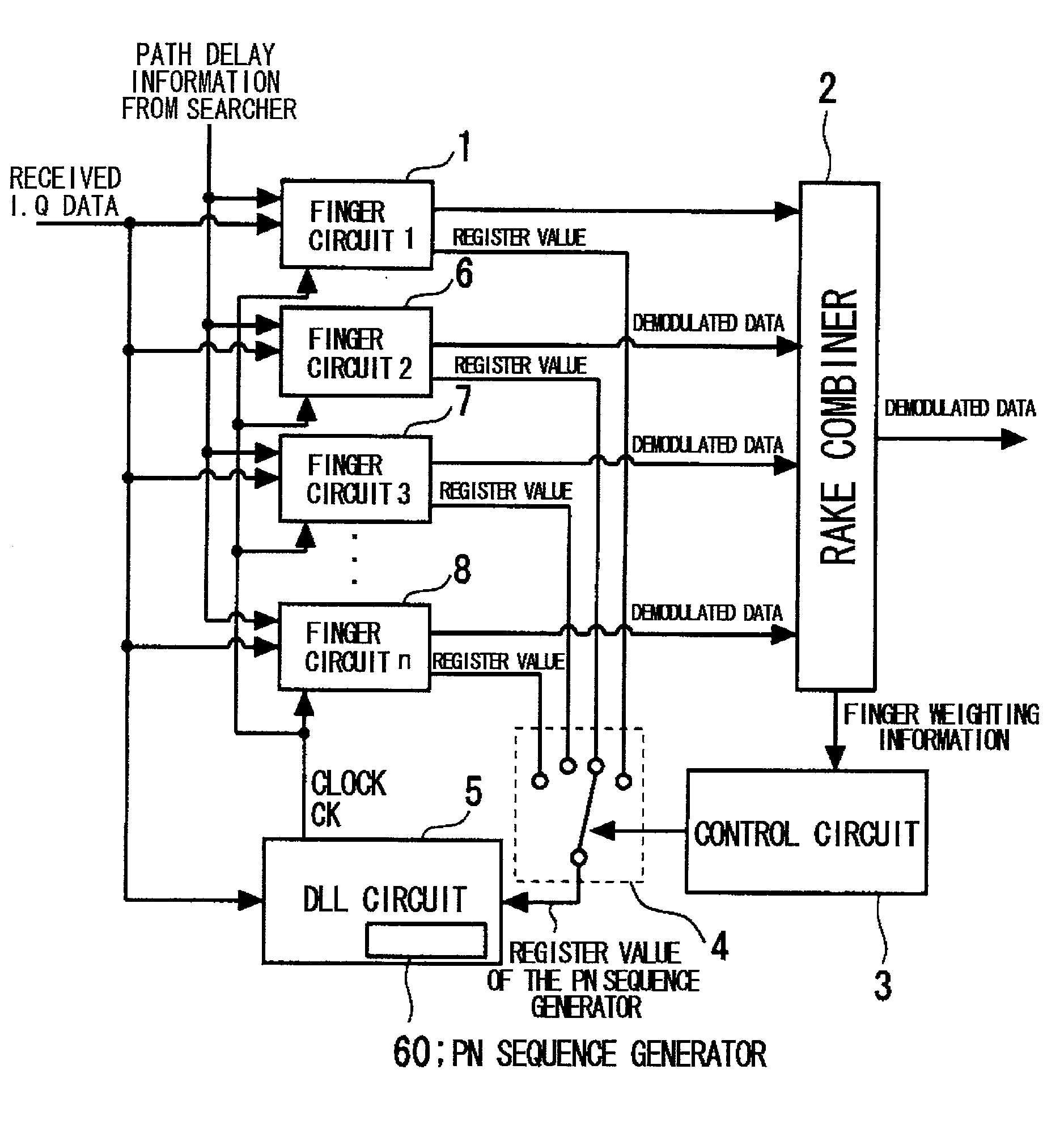
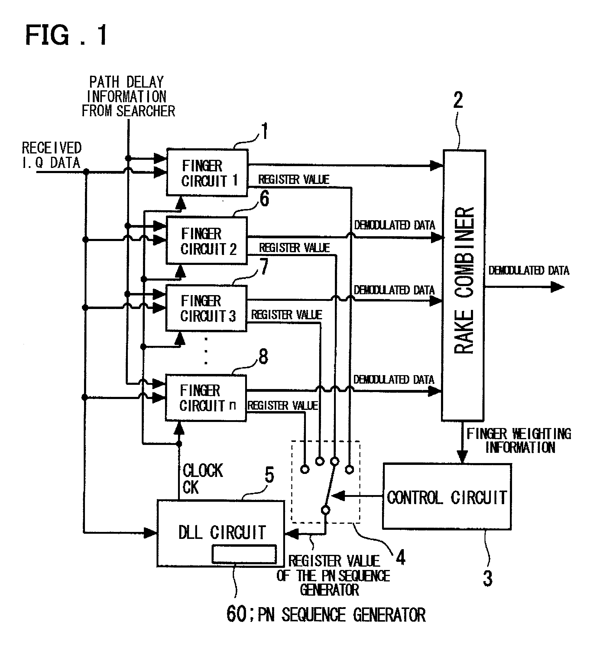
[0024] A preferred embodiment of the present invention is hereinafter explained. In the preferred embodiment of the present invention, a common one display lock loop (DLL) circuit is provided for plural finger circuits in a RAKE receiver, without providing a delay lock loop circuit (DLL circuit) for synchronization holding control for each finger circuit. The DLL circuit is caused by a changeover circuit to track an optimal finger circuit. The remaining finger circuits are adapted for being controlled by clock outputs from the DLL circuit.

[0025] In more detail, the control circuit 3 controls the changeover circuit 4, based on the finger-based information, such as weighting information as found in synthesising demodulated output signals of the respective finger circuits to select sequentially the finger circuits to be tracked by the DLL circuit 5.

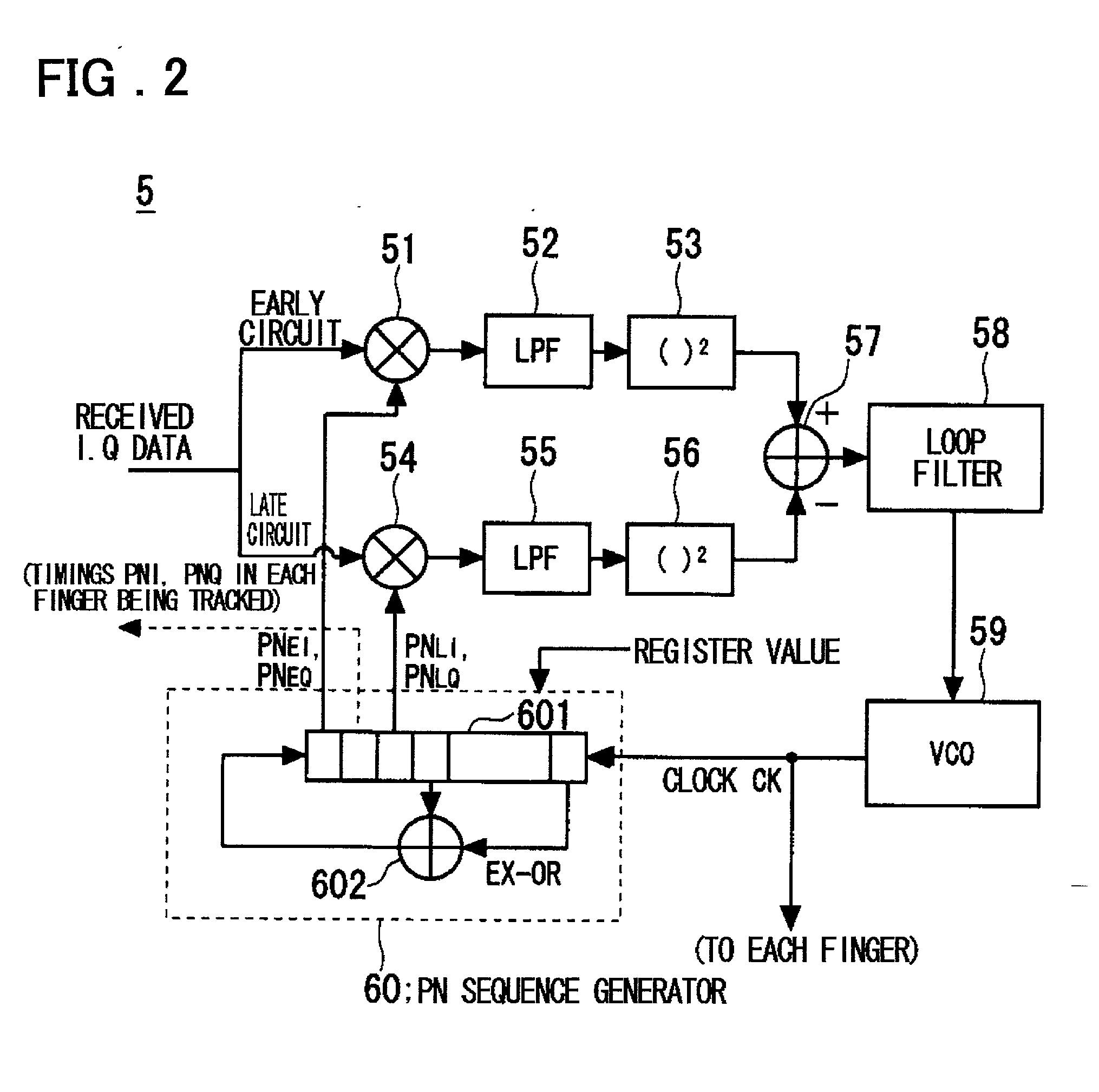
[0026] The clocks CK controlled by the DLL circuit 5 are fed to a PN sequence generator (13 in FIG. 3) of each finger circuit to execute a ...


PUM


Abstract

To provide an apparatus which reduces the scale of a reception circuit and the power consumption as the tracking function of tracking phase jitter of the multipath propagation route. A RAKE reception apparatus includes a plurality of finger circuits for receiving signals spectrum-spread by spread codes, despreading respective reception signals retrieved by a searcher adapted for retrieving respective paths from multipath reception signals for demodulating the signals, and a RAKE combiner for combining outputs of the plural finger circuits. Each of the plural finger circuits is provided with one DLL circuit without being provided with an inner DLL circuit. The finger circuits to be tracked by the DLL circuit are switched by a changeover circuit. There is provided a control circuit for controlling the changeover circuit based on the weighting information for each finger circuit to be found by the RAKE combiner for sequentially selecting the finger circuits to be tracked by the DLL circuit.

Description

[0001] This invention relates to a reception apparatus for a spread spectrum communication system. More particularly, it relates to a reception apparatus that may be used with advantage in particular in a cellular telephone system of the CDMA system.[0002] In the spread spectrum communication system, a carrier wave is modulated by transmission data and, in addition, the carrier wave is multiplied with the pseudorandom noise (PN) code, on the transmitting side, so that the carrier wave is transmitted as it is modulated with the PN code and as the frequency spectrum is spread. On the receiving side, the carrier wave is multiplied with the same PN code as that used on the transmitting side. If the PN code is the same PN code as and in phase with that used in transmission, despreading occurs to produce a modulated output, which is demodulated to derive reception data. In the spread spectrum communication system, as discussed above, the received signal is despread, so that the PN sequenc...

Claims


Application Information

Patent Timeline
Patent Type & Authority Applications(United States)
IPC IPC(8): H04B1/707H04B1/7085H04B1/7115H04L7/00
CPCH04B1/7085H04B1/7115H04B2001/70706H04B2201/70707
Inventor CHIBA, KENICHIRO
Owner NEC CORP
Why Eureka
Try Eureka