
CDMA receiving apparatus and method

a technology of cdma and receiving apparatus, applied in the field method, can solve the problems of cdma receiving apparatus not being able to receive radio signal, affecting the availability of cdma receiving apparatus resources, and affecting the reception of radio signal

Inactive Publication Date: 2002-02-14
NEC CORP
View PDF9 Cites 5 Cited by
  • Summary
  • Abstract
  • Description
  • Claims
  • Application Information

AI Technical Summary

Problems solved by technology

If the multi-path interference occurs, in a system whose radio channel bandwidth is as small as 30 kHz, for example, its receiving unit is not capable of receiving radio signal.
However, because in the spread spectrum communication system, its radio channel bandwidth is wide, the radio signal is always received although part of them is lost.
However, because the conventional CDMA receiving apparatus has such a structure which satisfies a maximum rate of high-speed data determined depending on system condition and a maximum number of simultaneous voice data processing users (the maximum number of simultaneous processing users generally requested in the form of high-speed data is smaller than the case of voice data) with a single reception processing block, there is such a problem that the availability of the resource of the CDMA receiving apparatus drops.
Therefore, the resources of the finger unit and RAKE combining unit become short, so that relatively, the resource of the searcher unit becomes excessive.
Thus, the resource of the searcher unit becomes short, so that relatively, the resources of the finger unit and the RAKE combining unit become excessive.
Therefore, voice reception processing in which real time processing is required cannot be carried out or may be delayed, when the number of users of high-speed data is increased and the resources in the finger unit and RAKE combining unit are consumed by the demodulation of the high speed data.

Method used


Image

  • CDMA receiving apparatus and method
  • CDMA receiving apparatus and method
  • CDMA receiving apparatus and method

Examples


Embodiment Construction

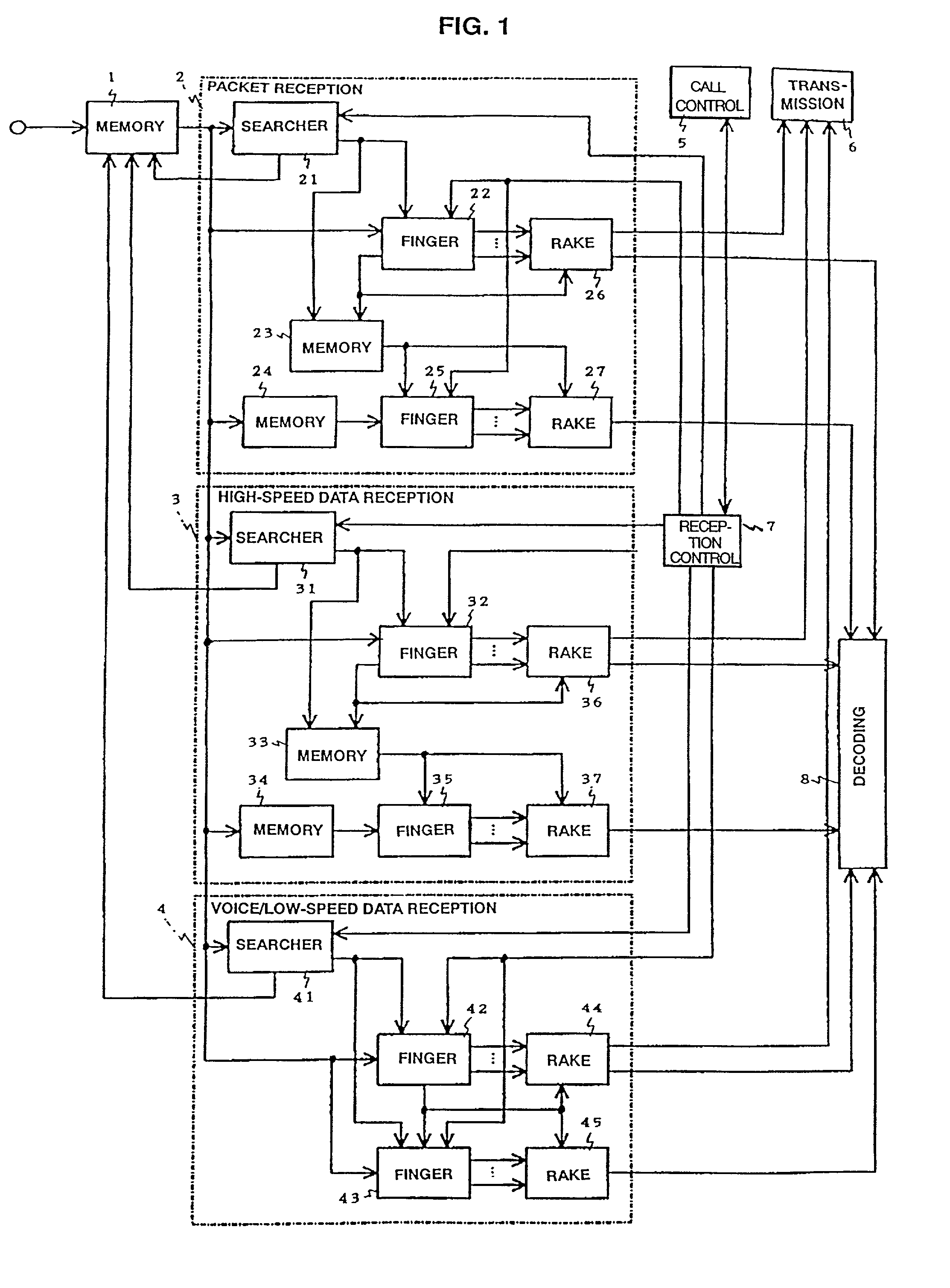
[0037] FIG. 1 is a block diagram of the CDMA receiving apparatus of the present invention. Referring to FIG. 1, the CDMA receiving apparatus of the present invention comprises a memory (for reception signal) 1, a packet reception processing block 2, a high-speed data reception processing block 3, a voice / low-speed data reception processing block 4, a call processing control unit 5, a CDMA transmission unit 6, a reception processing control unit 7 and a decoding unit 8.

[0038] The packet reception processing block 2 comprises a searcher unit 21, a finger unit (for control field) 22, a memory (for path information) 23, a memory (for data field) 24, a finger unit (for data field) 25, and RAKE combining units 26, 27.

[0039] The high-speed data reception-processing block 3 comprises a searcher unit 31, a finger unit (for control field) 32, a memory (for path information) 33, a memory (for data field) 34, a finger unit (for data field) 35 and RAKE combining units 36, 37.

[0040] The voice / low...


PUM


Abstract

The present invention provides a CDMA receiving apparatus capable of corresponding to the service types of data and system conditions flexibly and efficiently, so as to achieve such processing for electric power control, diversity control and the like, requested to have real-time property. A CDMA signal inputted into a memory is searched by searcher units of each reception processing block. Voice data and low-speed data are demodulated immediately by a finger unit for data field and a finger unit for control field, and combined by RAKE-combining units. Data fields of packet data and high-speed data are accumulated in memories for data field and demodulated by finger units for data field successively based on path information stored in memories for path information.

Description

[0001] 1. Technical Field of the Invention[0002] The present invention relates to a code division multiple access (CDMA) receiving apparatus and method.[0003] 2. Description of the Prior Art[0004] Recently, spread spectrum communication system highly insensitive to interference and disturbance has attracted public attention as one of communication methods applicable to mobile communication system. In radio communication systems using the spread spectrum signals, voice data or video data is modulated by PSK (Phase Shift Keying) or FSK (Frequency Shift Keying) or the like, and the modulated data is converted to wide-band base band signal using pseudo noise code (PN code: pseudo random noise code).[0005] On the other hand, a receiving unit carries out despreading the received radio frequency signal using the same code as the PN code used in the transmission unit and reproduces receiving data by carrying out digital demodulation according to PSK or FSK demodulation method.[0006] This ki...

Claims


Application Information

Patent Timeline
IPC IPC(8): H04B1/7117H04B1/707H04L7/00H04L29/08
CPCH04B1/7115H04B1/7117H04B2201/70703H04B2201/70707
Inventor HONDO, SHINYA
Owner NEC CORP
Learn More