
Red light emitting long afterglow photoluminescence phosphor and afterglow lamp thereof

a technology of photoluminescence phosphor and afterglow lamp, which is applied in the direction of discharge tube/lamp details, discharge tube luminescent screen, discharge tube/lamp details, etc., and can solve the problems of terrible reduction of the phosphorescent luminance, accelerated deterioration, and insufficient satisfaction

Inactive Publication Date: 2001-11-22
NICHIA CORP
View PDF1 Cites 72 Cited by
  • Summary
  • Abstract
  • Description
  • Claims
  • Application Information

AI Technical Summary

Benefits of technology

[0012] Further, even not only under emergency situation, if most huge buildings, such as department stores, school or factories, and regular buildings like stores and houses, are equipped with guide lamps with simple structure and lower cost, which allow users to see their feet from the time when they turn off the switches of the lights of a room, corridor or staircase, until they reach the exit, they would be more safe and comfortable.
[0015] In order to solve the above-mentioned problem, the inventor eventually achieved the present invention, finding out that the problem can be solved by introducing a specific coactivator into the rare earth oxysulfide phosphor activated by Europium, as a result of various researches to improve the long afterglow property and the phosphorescent luminance.

Problems solved by technology

The conventional substances used green light emitting ZnS:Cu phosphor as light storing phosphor, but did not give sufficient satisfaction.
Another is the dark coloration of the surface due to the precipitation of colloidal metallic zinc on the surface of the crystal of the phosphor because of the decomposition due to the ultraviolet, the problem being an terrible reduction of the deterioration of the phosphorescent luminance.
This deterioration accelerates particularly under the conditions of high temperature and humidity and usually, to ameliorate this drawback, a light proof treatment is applied on the surface of the ZnS:Cu phosphor, but the complete prevention still remains difficult.
The long afterglow light storing phosphor of this type emitting purplish-blue to green light, have been much studied and are presently used, but among light storing phosphors emitting red light, are only known CaS:Eu, Tm which have short afterglow properties and a poor chemical stability.
But, because electron rays excite this phosphor, it has been rarely studied as photoluminescence phosphor excited by ultraviolet rays.
However, if the backup power sources were broken down or its circuits were cut by the disaster, the guide lamps would turn off.
In such cases, a complex underground street, a long tunnel, nighttime multistory buildings or the like would become very dangerous situation.
Further, because the conventional guide lamps have complicated structure, it takes much time and high cost to install them.
Therefore, such guide lamps are rarely provided except the places where the Laws require to equip the same.
However, the conventional light storing substances are disadvantageous in that they are chemically unstable and are apt to be deteriorated by ultra-violet rays, high temperatures, moisture or the like.
Further, the afterglow of these light storing substances is dark and short.
Furthermore, sufficient light cannot be obtained by coating a supporting member with a light storing substance.

Method used


Image

  • Red light emitting long afterglow photoluminescence phosphor and afterglow lamp thereof
  • Red light emitting long afterglow photoluminescence phosphor and afterglow lamp thereof
  • Red light emitting long afterglow photoluminescence phosphor and afterglow lamp thereof

Examples


embodiment 34

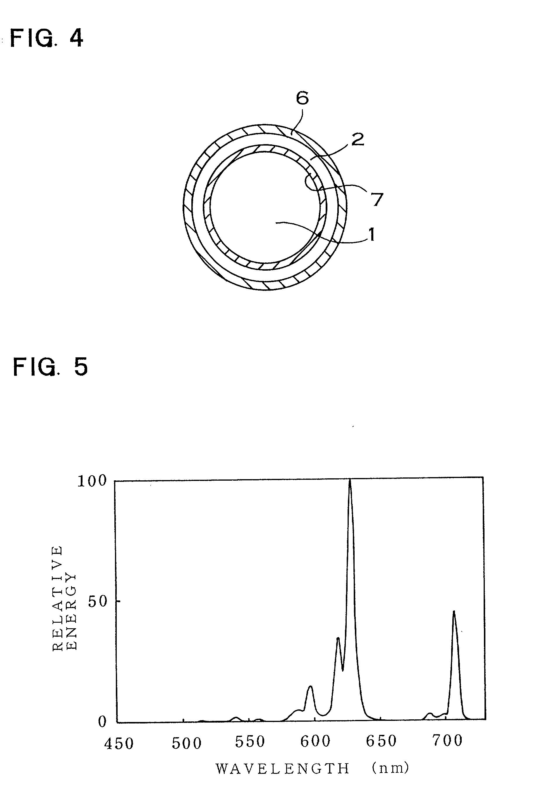
[0059] FIG. 5 is a graph showing the emission spectrum of the phosphor obtained by the present invention excited by 365 nm wavelength.

[0060] FIG. 6 is a graph comparing the afterglow characteristics of the phosphor obtained by the embodiments 22 and 46 of the present invention, with the afterglow characteristics of the conventional CaS:Eu,Tm phosphor.

embodiment 21

[0061] FIG. 7 is a graph comparing the afterglow characteristics of the phosphor obtained by the present invention, with the afterglow characteristics of the conventional Y.sub.2O.sub.2S:Eu phosphor.

[0062] FIG. 8 is a characteristics graph showing the relation the content x of the Eu of the Y.sub.2O.sub.2S:Eu.sub.x,Mg.sub.0.086,Ti.sub.0 030 phosphor and the phosphorescent luminance measured one minute after the termination of excitation of a black light lamp.

[0063] FIG. 9 is a characteristics graph showing the relation the content z of the Ti of Y.sub.2O.sub.2S:EU.sub.0 082,Mg.sub.0.028,Ti.sub.z phosphor and the phosphorescent luminance measured one minute after the termination of excitation of a black light lamp.

[0064] FIG. 10 is a characteristics graph showing the relation the average particle diameter of Y.sub.2O.sub.2S:Eu.sub.0.082,Mg.sub.0.086,Ti.sub.0.0-30 phosphor and the phosphorescent luminance measured one minute after the termination of excitation of a black light lamp.

TH...

example 1

[0065] showing a manufacturing method

[0066] This example does not show an embodiment of the present invention. To prepare a phosphor raw material, 46.5 g of Y.sub.2O.sub.3, 3.0 g of EU.sub.2O.sub.3 and 0.5 g of MgCO.sub.3 were prepared and put into a ceramic pot, then sufficiently blended by a ball mill. The resultant was a mixed raw material (hereinafter referred as raw material powder). Next 22.7 g of sulfur (S), 22.0 g of Na.sub.2CO.sub.3 as flux were added and mixed to the raw material powder, and its mixture was filled into an alumina crucible and heated for 6 hours at the temperature of 1100.degree. C. After heating, it was washed off the flux by water several times, and dried for 10 hours at the temperature of 120.degree. C. Finally a phosphor with its chemical formula Y.sub.2O.sub.2S:Eu.sub.0.-082,Mg.sub.0.028 was prepared.


PUM


Abstract

A red light emitting afterglow photoluminescence phosphor is a rare earth oxysulfide phosphor activated by Europium, which chemical formula is follows: Ln2O2S:Eux,My 0.00001<=x<=0.5 0.00001<=y<=0.3 wherein Ln is at least one selected from the group consisting of Y, La, Gd and Lu; M is a coactivator which is at least one selected from the group consisting of Mg, Ti, Nb, Ta and Gain the chemical formula.

Description

[0001] This is a continuation-in-part of International Application PCT / JP99 / 04412, filed Aug. 16, 1999.[0002] The present invention relates to a red light emitting long afterglow photoluminescence phosphor which emits light being excited by visible rays and ultraviolet rays, and an afterglow lamp coated with this phosphor. More specifically, the present invention relates to the red light emitting long afterglow photoluminescence phosphor which is a rare earth oxysulfide phosphor activated by Europium and coactivated by a specified element, and an afterglow lamp coated with this phosphor.TECHNICAL BACKGROUND[0003] Phosphors, which are irradiated by the light from the sunlight and from an artificial lighting, and also phosphors, which afterglow a relatively long time in dark places, are among phosphors, which are called light storing phosphors because this phenomenon can be repeated several times. Nowadays with the ever-increasing complication of social life, the interest of the popul...

Claims


Application Information

Patent Timeline
IPC IPC(8): C09K11/77C09K11/84H01J61/44H01J61/48
CPCC09K11/7789H01J61/44H01J61/48
Inventor MURAZAKI, YOSHINORIARAI, KIYOTAKA
Owner NICHIA CORP
Learn More