
Electrically conductive fabric

a fabric and electrical conductivity technology, applied in the field of electrical conductivity fabric, can solve the problems of fabric being often required to exhibit flame retardancy, fabric is often frayed, and the requirement of fabric is increasing, and achieves the effect of preventing the back leakage of resin and high electrical conductivity

Inactive Publication Date: 2001-11-01
SEIREN CO LTD
View PDF0 Cites 24 Cited by
  • Summary
  • Abstract
  • Description
  • Claims
  • Application Information

AI Technical Summary

Benefits of technology

[0016] It is an object of the present invention to solve the above-mentioned problems of the prior art and provide particularly a fabric capable of preventing the back leak of resin while ensuring flexibility and possessing high electrical conductivity and electromagnetic wave shielding property.
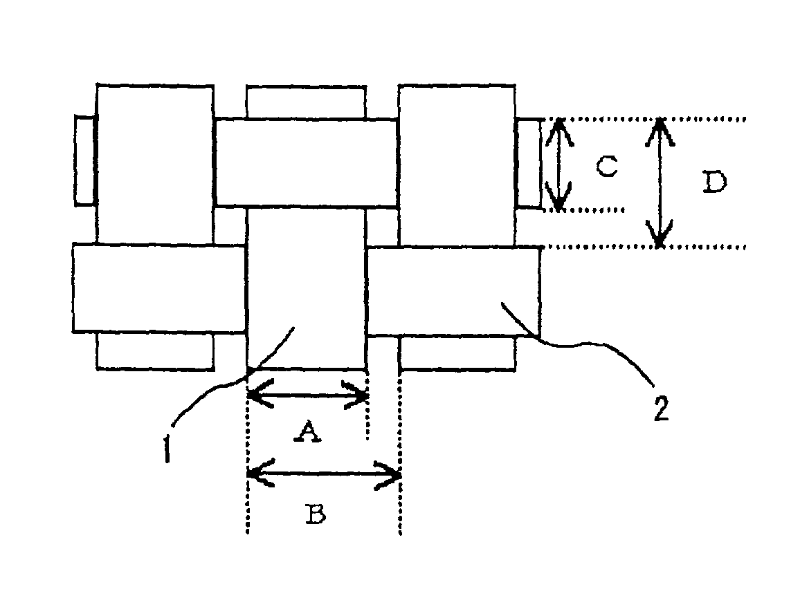
[0024] By thus increaing the warp density of the fabric, setting the percent fabric surface occupancy of warp at 90% to 110%, allowing the fabric surface to be covered mainly with warp, further by decreasing the weft density and setting the percent fabric surface occupancy of weft at 40% to 80%, it is possible to minimize pores formed in warp-weft intersecting points. Besides, the degree of freedom of weft increases and hence the fabric becomes more flexible.
[0028] By adopting the above-mentioned constitution there can be obtained an electrically conductive fabric which, in comparison with conventional fabrics, is more flexible, exhibits less back leak of resin at the time of resin coating, and possesses high electrical conductivity and electromagnetic wave shielding property.

Problems solved by technology

When the electrically conductive fabric is to be used in such a use, it is in many cases cut into a predetermined small size or into fine strips, so there arises the problem that the constituent yarns of the fabric are frayed.
Moreover, when the electrically conductive fabric is to be applied to such a use as mentioned above, the fabric is often required to exhibit flame retardancy and this requirement is increasing.
Generally, however, if the yarn density of a fabric is increased, the fabric tends to become less flexible.
If the fabric is plated, it becomes harder.
For example, therefore, if the electrically conductive fabric in question is wound round a urethane foam to afford a foam gasket and the foam gasket is used as a substrate grounding material, it is inferior in point of adhesion to a housing of an electronic device and is not desirable as an electromagnetic wave shielding material.
However, in the case where a fabric is produced using the yarns composed of ultrafine filaments or the finished yarns and is then plated, even if the fabric is flexible before the plating, a multifilament yarn which constitutes the fabric is restrained and becomes like a monofilament, so that the fabric becomes less flexible.
Moreover, by merely increasing the density of a fabric, it is difficult to completely minimizing pores formed at warp-weft intersecting points of the fabric and the remaining fiber-to-fiber pores make it difficult to improve the electromagnetic wave shielding property and electrical conductivity.
Also, there remains the problem of back leak of resin when the resin is applied in a post-processing.
Further, using an ultrafine yarn or a finished yarn and increasing the yarn density of a fabric results in an increase of cost and of the material surface area, with consequent increase in the amount of metal used in plating and likelihood of an increase of the plating cost.

Method used


Image

  • Electrically conductive fabric

Examples


example 1

[0056] A plain weave fabric using a 50d-24f polyester multifilament yarn as warp and weft was subjected to scouring and then heat-set at 190.degree. C. for 2 minutes to adjust the percent fabric surface occupancy of warp and that of weft to 95% and 72%, respectively. Thereafter, the fabric was etched in a solution comprising 50 g / L NaOH for about 10 minutes at 90.degree. C., and then rinsed and dried. Thereafter, the etched fabric was immersed in Pd / Sn colloidal catalyst solution for about five minutes at 40.degree. C. Thereafter, the primed fabric was then rinsed and immersed in a developer solution comprising 0.1N HBF.sub.4 for a few minutes. The fabric was rinsed and then immersed in an electroless copper bath operating at 40.degree. C., having the following composition that CuSO.sub.45H.sub.2O 15 g / L, Ethylenediaminetetraacetic acid (40%) 50 cc / L, NaOH 15 g / L, and HCHO (37%) 10 cc / L, so the fabric was copper plated. Separately, toluene was added to 100 parts by weight of Toacron...

example 2

[0057] A plain weave fabric using a 50d-36f polyester multifilament yarn as warp and weft was subjected to scouring and then heat-set at 190.degree. C. for 2 minutes to adjust the percent fabric surface occupancy of warp and that of weft to 99% and 78%, respectively. The fabric was then plated in the same manner as in Example 1. Separately, toluene was added to 100 parts by weight of Toacron SA6218 (an acrylic resin manufactured by Toupe Co.) and 1.5 parts by weight of a UD crosslinking agent (an isocyanate crosslinking agent manufactured by Dainichiseika Colour & Chemicals Mfg. Co.) to adjust the viscosity of the resulting resin solution to 25,000 cPs. The resin solution was then applied to the fabric surface in an amount of 5 g / m.sup.2 as solids content by a knife coating method, followed by drying at 130.degree. C. for 2 minutes. The performance of the thus-coated fabric is shown in Table 1.


PUM

PropertyMeasurementUnit
elongationaaaaaaaaaa
electrically conductiveaaaaaaaaaa
flexibilityaaaaaaaaaa

Abstract

An electrically conductive fabric plated with a metal is disclosed wherein a percent fabric surface occupancy of warp as a constituent of the fabric is 90% to 110% and that of weft is 40% to 80%. The electrically conductive fabric is superior in all of resin back leak preventing property, flexibility yarn fray preventing property, electrical conductivity and electromagnetic wave shieldability.

Description

[0001] The present invention relates to an electrically conductive fabric and more particularly to an electrically conductive fabric superior in all of back leak preventing property of resin, flexibility, yarn fray preventing property, electrical resistivity, and electromagnetic wave shielding property.[0002] It is known to form a metal coating on a fabric, thereby making the fabric electrically conductive, and use the thus-coated fabric as an electromagnetic wave shielding material or a grounding material.[0003] In such an application, the electrically conductive fabric is also required to be flexible because it is often used in an attached state to a housing of an electronic device.[0004] When the electrically conductive fabric is to be used in such a use, it is in many cases cut into a predetermined small size or into fine strips, so there arises the problem that the constituent yarns of the fabric are frayed.[0005] To prevent such a fray of the constituent yarns of the electrica...

Claims


Application Information

Patent Timeline
Patent Type & Authority Applications(United States)
IPC IPC(8): D06M11/00D03D15/283D06M11/83D06M101/00H05K9/00
CPCD03D15/00D06M11/83H05K9/009D03D15/0083D10B2201/02D10B2321/10Y10T428/2929D10B2331/04D10B2401/16Y10T428/2915Y10T428/2967Y10T428/2913Y10T428/2924D10B2331/02Y10T442/3081Y10T442/3252Y10T442/3179Y10T442/3317Y10T442/3407Y10T442/3301Y10T442/2418Y10T442/30Y10T442/322Y10T442/339Y10T442/3073D03D15/283
Inventor TAKAGI, SUSUMUORITA, SHIGEKAZU
Owner SEIREN CO LTD
Learn More