
Fuel cell, and collector plate thereof

a fuel cell and collector plate technology, applied in the field of fuel cells, can solve the problems of unit cells failing to generate the desired electromotive force, reducing power generation efficiency, and relatively low electromotive force generated by those unit cells

Inactive Publication Date: 2001-09-06
TOYOTA JIDOSHA KK
View PDF0 Cites 25 Cited by
  • Summary
  • Abstract
  • Description
  • Claims
  • Application Information

AI Technical Summary

Benefits of technology

[0013] The gas passage of a collector plate located remotely from an inlet of the supply manifold, on the other hand, is supplied with the reaction gas at a relatively reduced pressure. In such a gas passage, therefore, the influence of the constricting effect of the discharge hole becomes great, so that the reaction gas becomes less apt to be discharged. As a result, the amount of the reaction gas supplied to the gas passage via the supply hole becomes less in a collector plate located remotely from the inlet of the supply manifold than in a collector plate located near the inlet.
[0014] In the above-described aspect of the invention, however, the restriction on flow by the constricting effect of the discharge hole is reduced, so that the reaction gas can be promptly discharged from the gas passage via the discharge hole. Therefore, even in the case of a collector plate disposed remote from the inlet of the supply manifold, at least a predetermined amount of the reaction gas can be caused to flow through the collector plate. Thus, the bias of distribution of the reaction gas to the gas passages of the unit cells that constitute a fuel cell can be reduced, and the distribution characteristic can be improved.

Problems solved by technology

However, in the aforementioned fuel cell in which each reaction gas is supplied and discharged between the corresponding gas passages and the manifolds common to those gas passages, there is an unignorable problem as follows, regarding the amount of flow of each reaction gas and the distribution thereof.
Therefore, whereas sufficient amounts of the reaction gasses are supplied to unit cells that are relatively close to the inlets of the supply manifolds, the amounts of the reaction gasses supplied into the gas passages of unit cells that are relatively remote from the inlets of the supply manifolds become insufficient, and therefore the electromotive forces generated by those unit cells become relatively low.
Thus, in the fuel cell in accordance with the relative art, the distribution of each reaction gas to the gas passages is biased, so that some of the unit cells fail to generate a desired electromotive force.
Therefore, a reduction in power generating efficiency is inevitable.

Method used


Image

  • Fuel cell, and collector plate thereof
  • Fuel cell, and collector plate thereof
  • Fuel cell, and collector plate thereof

Examples


Embodiment Construction

[0020] A preferred embodiment of the invention will be described hereinafter with reference to FIGS. 1 to 4.

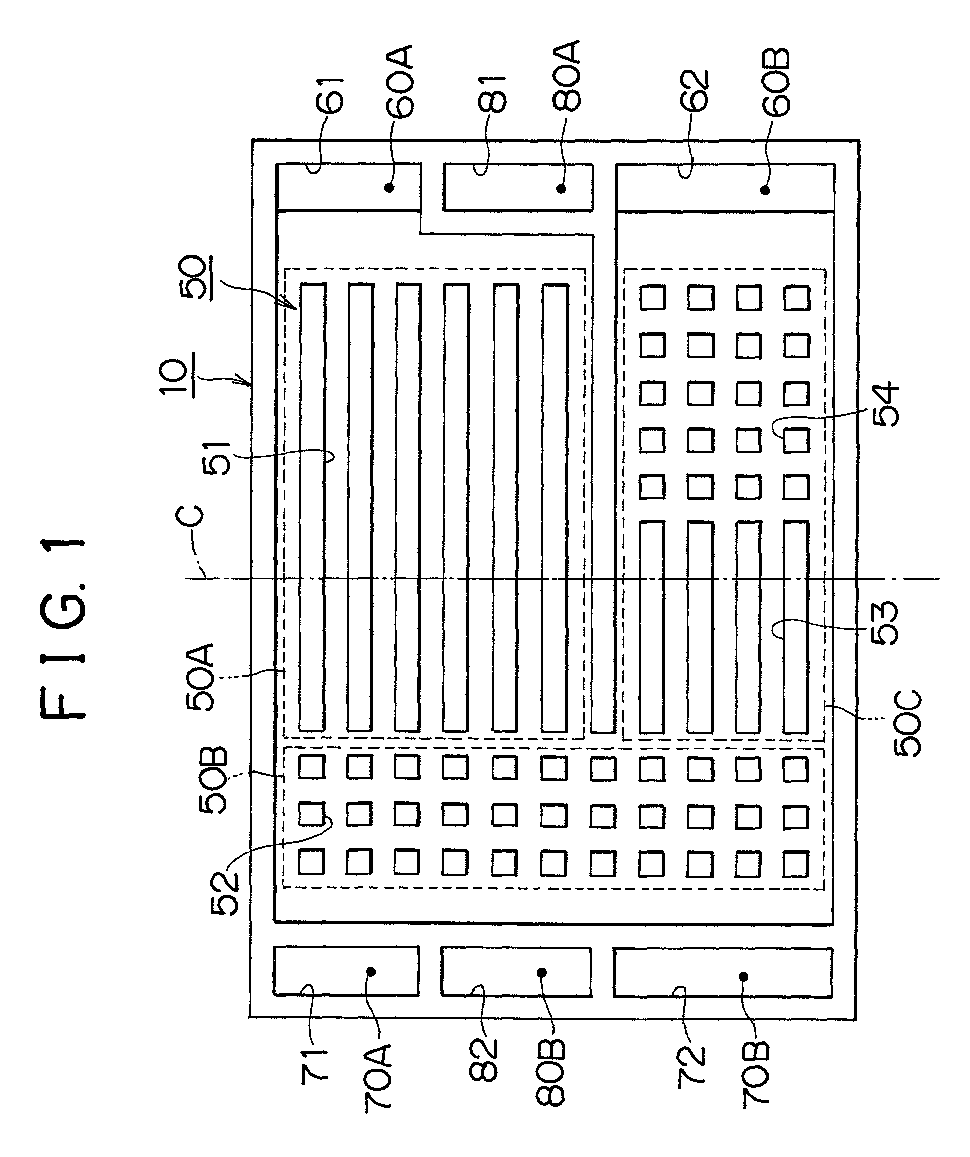
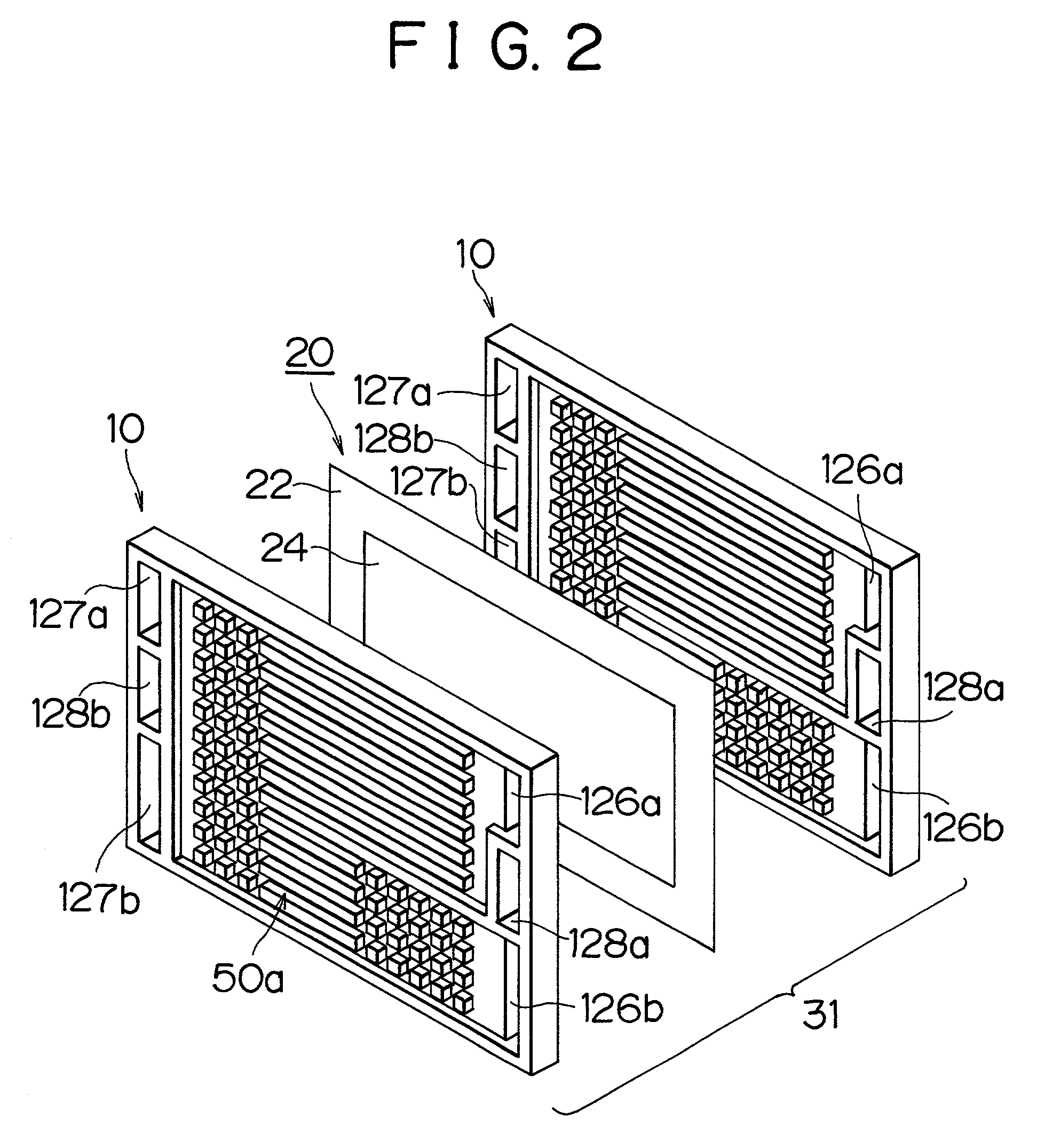
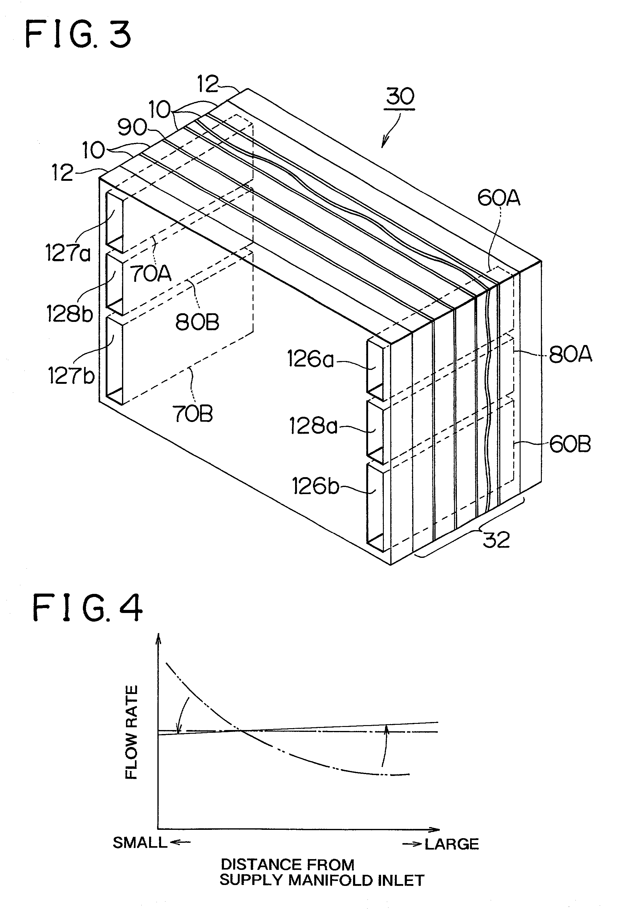
[0021] FIG. 1 illustrates a plan view construction of a collector plate 10 used in a polymer electrolyte fuel cell 30 in accordance with the embodiment. FIG. 2 illustrates an exploded view construction of a unit cell 31 of the fuel cell 30. FIG. 3 illustrates a perspective view construction of the fuel cell 30.

[0022] Referring to FIG. 3, the fuel cell 30 includes a stack 32 formed by alternately stacking a plurality of baseboards 20 and a plurality of collector plates 10, and two side plates 12 sandwiching the stack 32 on opposite sides thereof. The stack 32 is disposed so that when the fuel cell 30 is placed in a usable state, the stacking direction of the stack 32 coincides with a direction perpendicular to the direction of gravity (vertical direction in each drawing).

[0023] Each baseboard 20 has an electrolyte film 22, and reaction electrodes (a negative electrode and a pos...


PUM


Abstract

A fuel cell and a collector plate thereof that are able to improve the characteristic of distribution of reaction gasses to gas passages. Each collector plate of the fuel cell has reaction gas-conveying gas passages that are formed in stacking surfaces that face adjacent electrolyte films. Each gas passage is provided with a supply hole for distributing and supplying a reaction gas and a discharge hole for discharging the reaction gas from the gas passage. In a state where collector plates are stacked with electrolyte films placed therebetween, the supply holes connect to form a supply manifold, and the discharge holes connect to form a discharge manifold. The opening area of each discharge hole is set greater than the opening area of each supply hole.

Description

INCORPORATION BY REFERENCE[0001] The disclosure of Japanese Patent Application No. 2000-060111 filed on Mar. 6, 2000 including the specification, drawings and abstract is incorporated herein by reference in its entirety.[0002] 1. Field of the Invention[0003] The invention relates to a fuel cell that has a stack formed by stacking a plurality of collector plates and a plurality of electrolyte films provided with reaction electrodes, supply manifolds formed in the stack for distributing and supplying reaction gasses to gas passages formed between the electrolyte films and the collector plates, and discharge manifolds into which reaction gases from the gas passages are discharged. The invention also relates to a collector plate of a fuel cell, the collector plate having gas passages, and supply holes and discharge holes for forming the manifolds.[0004] 2. Description of the Related Art[0005] A fuel cell has a stack body having a stack structure formed by stacking unit cells. Each unit ...

Claims


Application Information

Patent Timeline
IPC IPC(8): H01M8/02H01M8/10H01M8/24
CPCH01M8/0247H01M8/0258H01M8/026H01M2300/0082Y02E60/50H01M8/2483H01M8/241H01M8/0267H01M8/2457H01M8/0265
Inventor TSUYOSHI, TAKAHASHI
Owner TOYOTA JIDOSHA KK
Learn More