
Electric system

a technology of electric systems and control devices, applied in the field of electric systems, can solve the problems of large space for additional components, high energy consumption, and heat loss normally occurring during the operation of electric components or control devices, and achieve the effects of reducing and increasing the cost of electric components

Inactive Publication Date: 2001-08-30
MANNESMANN SACHS AG
View PDF0 Cites 37 Cited by
  • Summary
  • Abstract
  • Description
  • Claims
  • Application Information

AI Technical Summary

Benefits of technology

[0028] The use of the coolant circuit of an air conditioning system for cooling the component part has a number of advantages. Temperature fluctuations which may occur when an electric component and / or a control device is to be cooled in a motor vehicle by the coolant circuit of the internal combustion engine are eliminated. The temperature of the coolant in a known cooling system of this type depends on the different operating states of the vehicle and therefore can not vary substantially. However, an air conditioning system generates a substantially constant and low temperature at all times independent of the different operating states of the motor vehicle.
[0051] Therefore, according to the present invention, a motor vehicle is provided with a simply designed, inexpensive, space-saving and nevertheless effective cooling device for electric components of a starter generator system which is particularly suitable for cooling the power electronics of the starter generator system.

Problems solved by technology

Heat loss normally occurs during the operation of an electric component or control device and must dissipated.
However, this solution is very energy-intensive because the individual elements of the cooling device such as, for example, pumps must be driven.
Further, a solution of this kind requires a relatively large amount of space for the additional components which is very disadvantageous particularly in the automobile industry because of the limited space available in the engine compartment.
However, the coolant of the internal combustion engine already has a relatively high temperature when entering the power electronics.

Method used


Image

  • Electric system
  • Electric system
  • Electric system

Examples


Embodiment Construction

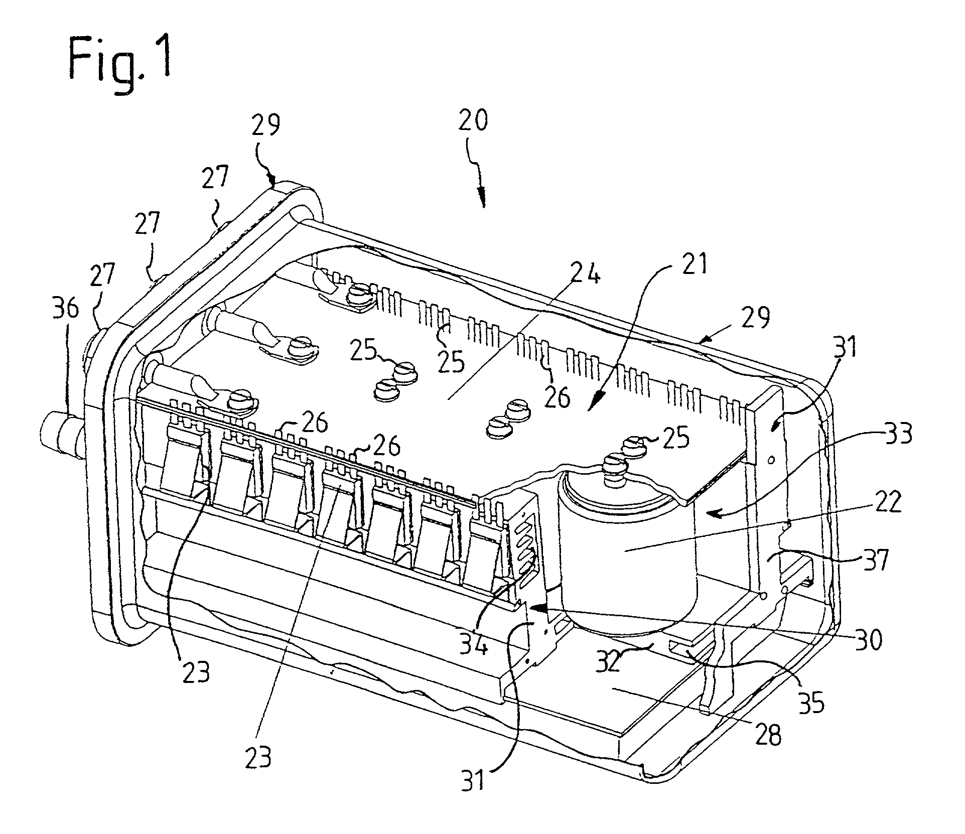
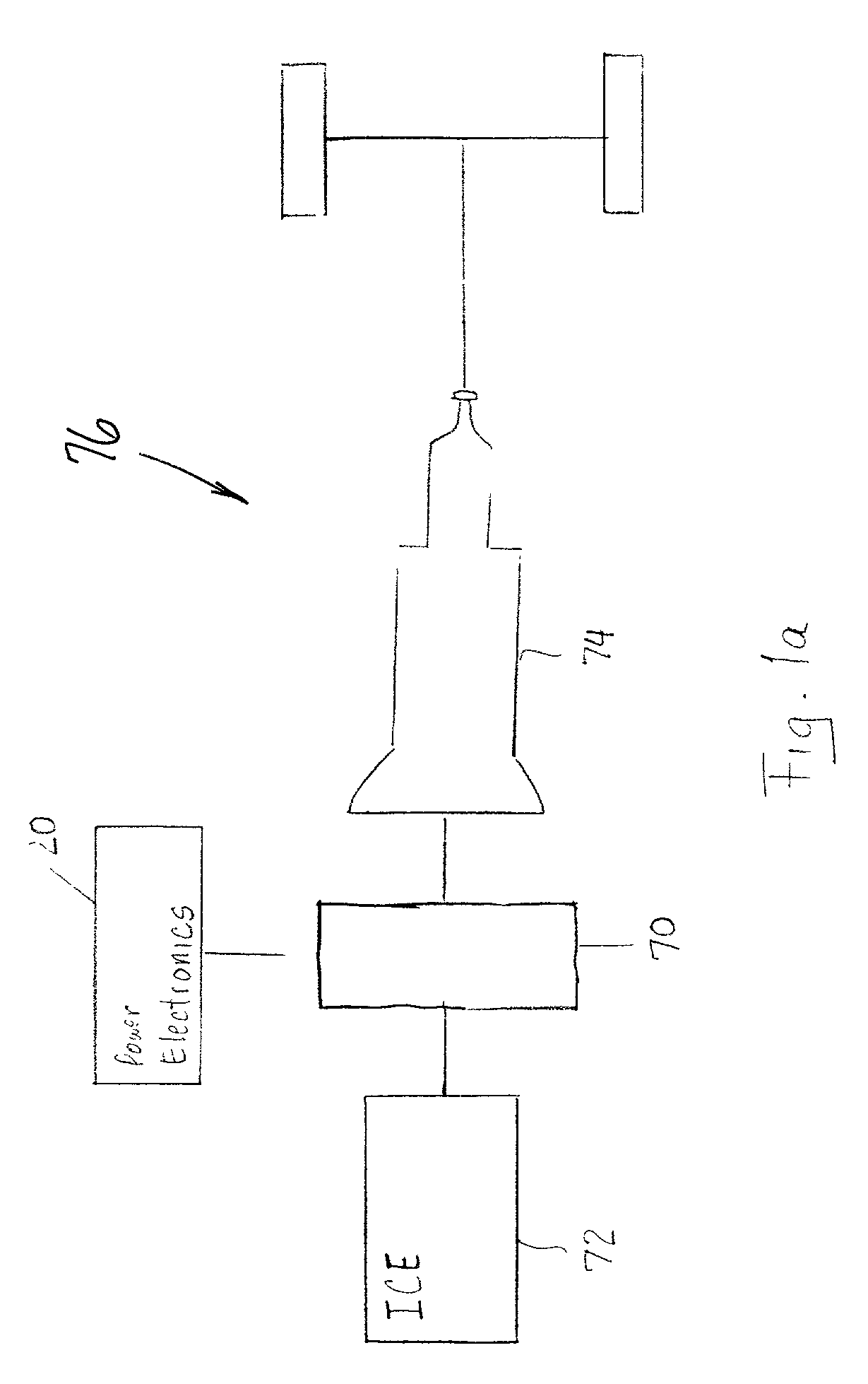
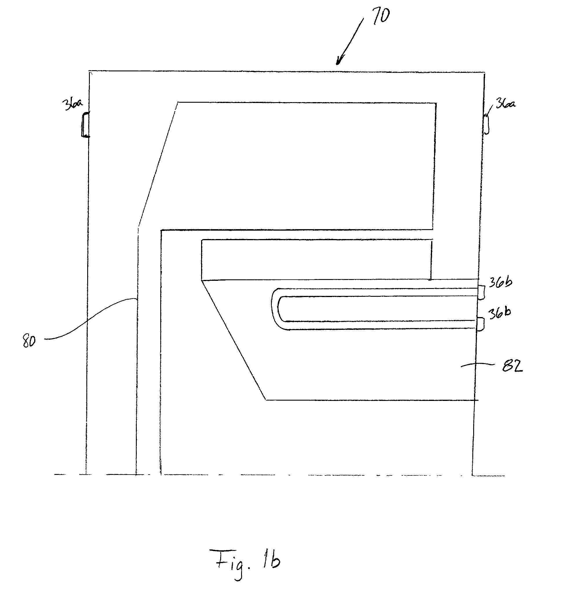
[0062] FIGS. 1 and 1a show power electronics 20 for controlling an electric machine 70, wherein the electric machine 70 is a starter generator constructed as a permanently excited synchronous machine arranged in the drive train of a vehicle 76. FIG. 1a shows that the electric machine 70 may be connected between an Internal Combustion Engine (ICE) 72 and a transmission 74. Accordingly, the electric machine 70 may be used as a starter for the ICE 72 and may be used as a generator for generating electricity when the ICE 72 is running. The power electronics 20 comprise a component part 11 (see FIGS. 2 to 4) of a control device which is to be cooled according to an embodiment of the present invention. However, the component part 11 may alternatively comprise the electric machine 70. The connection of the component part 11 to a cooling circuit will be explained more fully with reference to FIGS. 2 to 4.

[0063] The power electronics 20 have a housing 29 produced as an aluminum deep-drawn pa...


PUM


Abstract

The description relates to an electric system with at least one electric component such as an electric machine and at least one control device for controlling the electric component. The electric system further comprises a cooling device for cooling at least one component part of the at least one electric component or the at least one control device. To achieve an effective and stable cooling of the component part, the cooling device has an air conditioning system with a coolant circuit including an air conditioning compressor, a condenser, an evaporator, and line elements connecting these. The at least one component part to be cooled is arranged in the coolant circuit.

Description

[0001] 1. Field of the Invention[0002] The present invention relates to an electric system having a component, a controlling device for controlling the component, and a cooling device for cooling one of the controlling device and the component. The present invention further relates to a motor vehicle having an air conditioning system for cooling the electric system.[0003] 2. Description of the Related Art[0004] Electric systems usually have at least one electric component which is controlled by at least one control device. Electric systems of this kind are very common in practice.[0005] Electrical systems are used, for example, in the automotive industry in a wide variety of functions. For instance, the electric component may be an electric drive. The use of electric components in the drive arrangement of motor vehicles such as, for example, in the drivetrain is also very common.[0006] The electric drive may, for example, be an electric machine such as a synchronous machine for gene...

Claims


Application Information

Patent Timeline
IPC IPC(8): B60H1/32F25D19/00H05K7/14H05K7/20
CPCB60H1/323B60K6/485B60K2001/003F25D19/00H05K7/20881H05K7/20936Y02T10/6226B60H2001/00307Y02T10/62
Inventor WEIMER, JURGEN
Owner MANNESMANN SACHS AG
Learn More