Magnetic-head supporting mechanism

a support mechanism and magnetic head technology, applied in the direction of maintaining the head carrier alignment, recording information storage, instruments, etc., can solve the problems of significant differences in damage degree, and achieve the effect of improving impact resistance and reducing contact damag

Inactive Publication Date: 2001-07-26
HITACHI GLOBAL STORAGE TECH JAPAN LTD
View PDF0 Cites 1 Cited by
  • Summary
  • Abstract
  • Description
  • Claims
  • Application Information

AI Technical Summary

Benefits of technology

[0008] In view of this point, it is an object of this invention that when the magnetic-disc apparatus is subjected to a large impact to cause the slider to jump from the disc surface and the slider then re-contacts the disc surface, the contacting position of the slider is controlled to prevent the contact area from being reduced in order to reduce contact damage, thereby improving the impact resistance.
[0010] It is another object of this invention to improve the impact resistance of the magnetic-disc apparatus and to provide a magnetic-head supporting mechanism that allows the slider to be easily mounted on the suspension and that has an excellent assembly capability.
[0013] The gimbal has a low rigidity sufficient to avoid restraining the movement of the slider in the out-of-plane direction perpendicular to the floating surface of the slider, (perpendicular to the floating surface) while having a high rigidity in the in-plane direction (parallel to the floating surface).
[0017] According to this configuration, even when a large impact is applied to the magnetic-disc apparatus to cause the slider to jump from the disc surface and to start rotating around the pivot through a large angle, the gimbal, which rotates with the slider, contacts the roof portion to restrict the rotation of the slider. This enables the position (state) of the slider in which it contacts the disc surface after a jump to be controlled. Specifically, the substantial rotation of the slider causes the edges of the bleed surface of the slider (the four corners of the slider) or of the floating surface to contact the disc surface, thereby preventing the disc from being damaged due to a high contact area pressure (stress) caused by a small contact area.

Problems solved by technology

Thus, even if the slider contacts the disc surface at the same speed and acceleration, the contact area pressure (stress) significantly varies depending on the contact areas of the slider and disc surface, that is, the position of the slider in which it collides against the disc surface, resulting in significantly different degrees of damage.

Method used


Image

  • Magnetic-head supporting mechanism
  • Magnetic-head supporting mechanism
  • Magnetic-head supporting mechanism

Examples


first embodiment

[0056] this invention is described with reference to FIGS. 1 to 9.

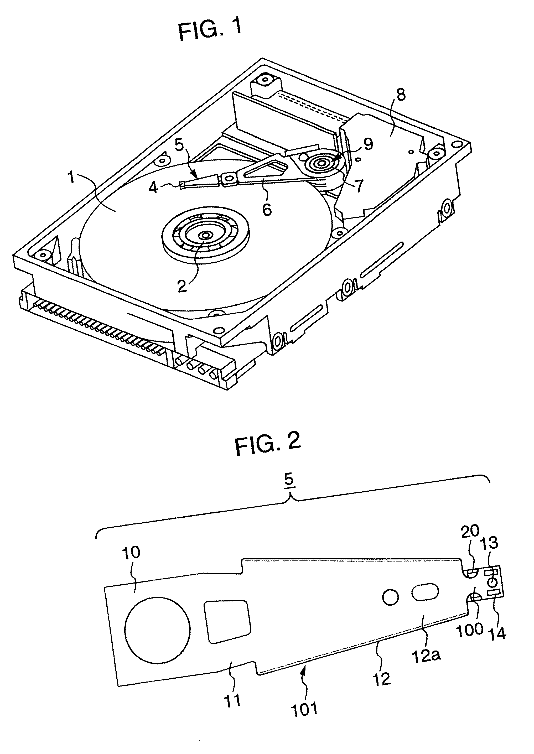
[0057] FIG. 1 shows a general view of a magnetic-disc apparatus in which a magnetic-head supporting mechanism according to a first embodiment of this invention is mounted.

[0058] A magnetic discs 1 on which information is recorded is laminated on a spindle 2. A magnetic head (not shown) used to record and reproduce information on and from the magnetic disc is mounted on a slider 4 of a magnetic-head supporting mechanism 5. The magnetic-head supporting mechanism 5 is joined with the arm 6. The magnetic head is placed at a predetermined radial position by a carriage 9 consisting of a pivot bearing 7 and a voice coil motor 8. These mechanisms are mounted in a lunch-box-shaped base and are sealed by a cover (not shown). The present magnetic-head supporting mechanism improves impact resistance to enable recording and reproduction at a high density even when the magnetic-disc apparatus is configured as a portable type.

[0059]...

seventh embodiment

[0105] FIGS. 17 and 18 show this invention. This embodiment differs from the first embodiment in that the gimbal and the load beam are integrated together and that the pivot is omitted.

[0106] A slider 704 is mounted on a mounting portion 724, which connects to a horizontal frame 725, and two flexible finger portions 722 extend from the respective sides of the horizontal frame to connect to a flange portion 712. At a slider-side end of a flat portion 712a of the flange, a roof 740 is provided over a rear surface 704a of the slider. The roof 740 is molded simultaneously with the press working of an L-shaped bent portion 712b of the flange portion 712. FIG. 18 shows that the roof 740 is provided over the rear surface 704a of the slider. The roof 740 has the same effects as in the first embodiment and prevents the slider 704 from rotating through a large angle due to an impact. That is, the roof 740 restrains the rotation of the slider to reduce the contact angle between the slider and ...

eighth embodiment

[0107] this invention is described with reference to FIGS. 19, 20, and 21. In FIG. 20 the slider is not mounted. This embodiment differs from the seventh embodiment in that instead of the roof, a flange portion 812 is joined with a mounting portion 824 using a FPC 50. The FPC 50 has a loop-like flexed portion 50a so as not to hinder the slider from floating.

[0108] If an impact is input, the flexed portion 50a of the FPC 50 restrains the movement of the slider 4 as shown in FIG. 21. This prevents the slider 4 from rotating through a large angle due to the impact. Thus, this embodiment provides effects similar to those of the seventh embodiment. Of course, by providing the roof as shown in the first to seventh embodiments, the rotation of the slider caused by the impact can be reliably restrained. Although this embodiment connects the mounting portion 824 and the flange portion 812 together using the FPC, similar effects can be obtained using an elastic material other than the FPC tha...


PUM

PropertyMeasurementUnit
angleaaaaaaaaaa
angleaaaaaaaaaa
widthaaaaaaaaaa

Abstract

If a large external impact is applied to a magnetic disc apparatus, a slider jumps from a disc surface and rotates. When the slider jumps and rotates, its edges re-contact the disc surface to damage this surface. To reduce the rotation angle of the slider to control its position if an impact is effected, the present invention provides a roof on a load arm to reduce the contact angle at which the slider contacts the disc surface in order to relax the impact upon a contact.

Description

[0001] 1. Field of the Invention[0002] The present invention relates to a magnetic-head supporting mechanism for a magnetic-disc apparatus, and in particular, to a magnetic-head supporting mechanism that is excellent in impact resistance.[0003] 2. Description of the Related Art[0004] It has been reported that when a large impact is applied to a conventional magnetic-disc apparatus in the direction perpendicular to a disc surface, a slider jumps up from the magnetic disc surface, is tilted while floating, and falls from the angle of a slider floating rail to contact and damage the disc surface (IEEE TRANSACTION ON MAGNETICS Vol. 31, No. 6, pp. 3006 to 3008: NOVEMBER, 1995). This article also reports that a "jump stop" is effectively provided on the slider in order to reduce the damage to the disc caused by an impact.[0005] In addition, JP-A-8-102159 discloses a mechanism comprising a pin protrusion (a limiter section) on a cover or on a base of a magnetic-disc apparatus wherein if th...

Claims


Application Information

Patent Timeline
Patent Type & Authority Applications(United States)
IPC IPC(8): G11B5/48G11B5/60G11B21/21
CPCG11B5/4826G11B5/4833
Inventor TOKUYAMA, MIKIOKATOU, YUKIOSHIMIZU, JYOUSEIKOJIMA, YASUONISHIDA, HIROSHIUEFUNE, KOUKI
Owner HITACHI GLOBAL STORAGE TECH JAPAN LTD
Why Eureka
Try Eureka