
Resonance ionization filter for secondary ion and accelerator mass spectrometry

a secondary ion and accelerator mass spectrometry technology, applied in the field of resonance ionization filter for secondary ion and accelerator mass spectrometry, can solve the problems of loss of the petrologic context of the sample, signal undetectable or highly imprecise, and no alternative to this technique, so as to reduce saturation irradiance, lower velocities, and higher residence times

Active Publication Date: 2022-11-15
THE UNITED STATES OF AMERICA AS REPRESENTED BY THE SECRETARY OF THE NAVY
View PDF1 Cites 0 Cited by
  • Summary
  • Abstract
  • Description
  • Claims
  • Application Information

AI Technical Summary

Benefits of technology

[0015]Our invention mitigates the drawbacks of SIMS and RIMS by adding a RIF to a SIMS instrument, yielding atomically and elementally specific measurements from micrometer-sized volumes of material.

Problems solved by technology

For small (micrometer-sized) samples, there are no alternatives to this technique, since chemistry is not feasible.
It is often the case, however, that nuclear isobars (e.g., 87Rb and 87Sr) cannot be measured by increasing the mass resolving power (MRP, typically defined as the full width at 10% peak height) of the mass spectrometer because of the simultaneous loss of ion transmission (essentially making the signals undetectable or highly imprecise).
The generally accepted method for removing nuclear isobaric interferences in mass spectrometry is to perform separation chemistry on the sample prior to measurement (e.g., by inductively coupled plasma (ICP)-MS, thermal ionization MS (TIMS), or AMS), however this results in a loss petrologic context of the sample; furthermore, chemistry is not practical for individual microanalytical samples routinely measured by SIMS (e.g., micrometer-sized particles).
However, RIMS is challenged by non-resonant ionization and molecules within the sample plume for many matrices (such as oxides), and the technical challenge of overlapping the ionization lasers with the expanding plume above the sample while achieving saturation of the atomic excited states.
The duty cycle of ToF-MS instrument is very low compared to dynamic SIMS, which can affect instrument stability and precision over long measurements.

Method used


Image

  • Resonance ionization filter for secondary ion and accelerator mass spectrometry
  • Resonance ionization filter for secondary ion and accelerator mass spectrometry
  • Resonance ionization filter for secondary ion and accelerator mass spectrometry

Examples


example 1

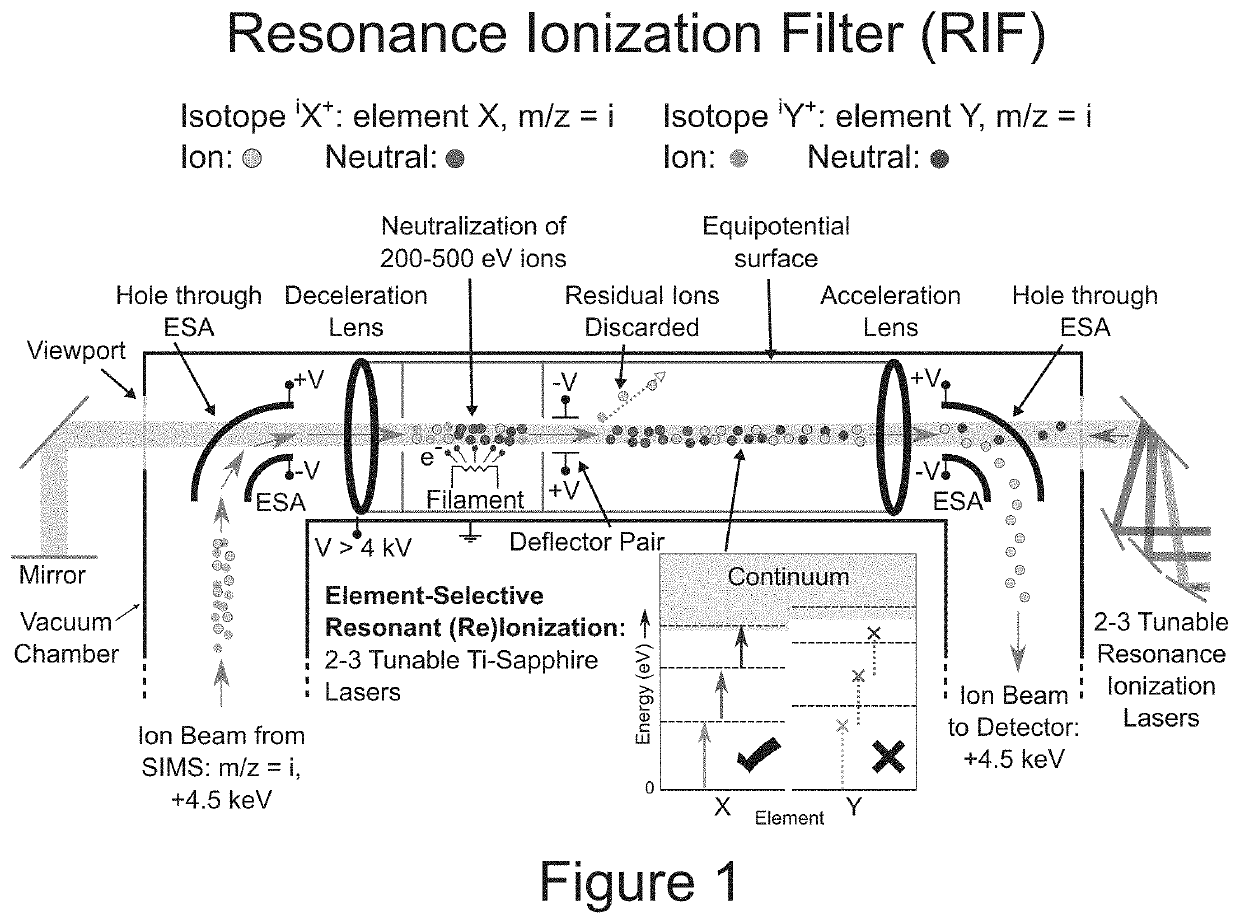
[0026]The RIF will incorporate four processes that in combination remove nuclear isobars from SIMS-like ion beams—deceleration, neutralization, resonant reionization, and re-acceleration—prior to ion detection.

[0027]FIG. 1 shows a schematic of the RIF.

[0028]Neutralization of the SIMS ion beam is performed using an electron source (e.g., W filament or plasma) or a gas cell.

[0029]Following the neutralizer, a set of deflector plates will be used to deflect any non-neutralized beam fraction into a detector for a measure of neutralization efficiency and to ensure that ions reentering the NAUTILUS beamline are only those that have been resonantly reionized.

[0030]The lasers for a resonance ionization system are pulsed at a specific repetition rate, while the ion signal from the dynamic SIMS is continuous.

[0031]Deceleration of the 4.5 keV SIMS ions down to a few hundred eV is therefore required to maximize the flight time of the ions in the RIF and increase the interaction probability with ...

example 2

[0042]We estimate the efficiency of the system we designed for the NAUTILUS (based on equations 1-5) to be up to 80% based upon the types of lasers available and calculations of the ion beam profile from the SIMS (i.e. a loss of only 20% of the ions of interest).

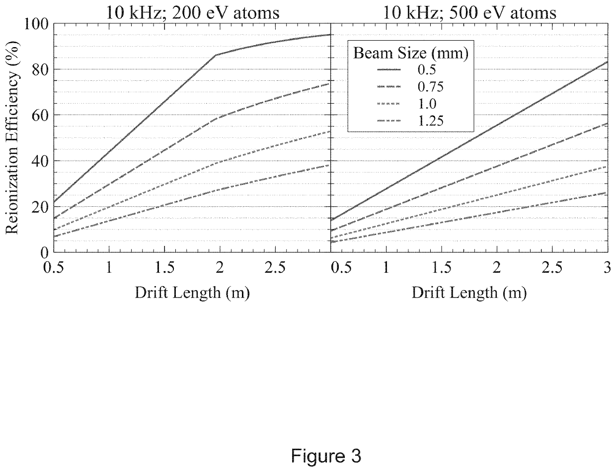
[0043]Ion optical models of the SIMS ion beam using SIMION were fed into the equations below (e.g., beam size, energy, dispersion, etc.). We calculated the efficiency of the reionization component of the RIF by determining the residence time of the neutrals in the drift tube (Eq. 1), each laser's irradiance (power density) (Eq. 2), the number of laser pulses per neutral in the drift tube (Eq. 3), the ionization probability (Eq. 4), and the overall efficiency (Eq. 5). Note, units have been stripped from the following equations for clarity. For all equations: L=drift length, V=ion / neutral energy, M=atom mass, p=average laser power, f=laser frequency, w=laser pulse width, s=laser beam size, t=residence time of atoms overlapping...

example 3

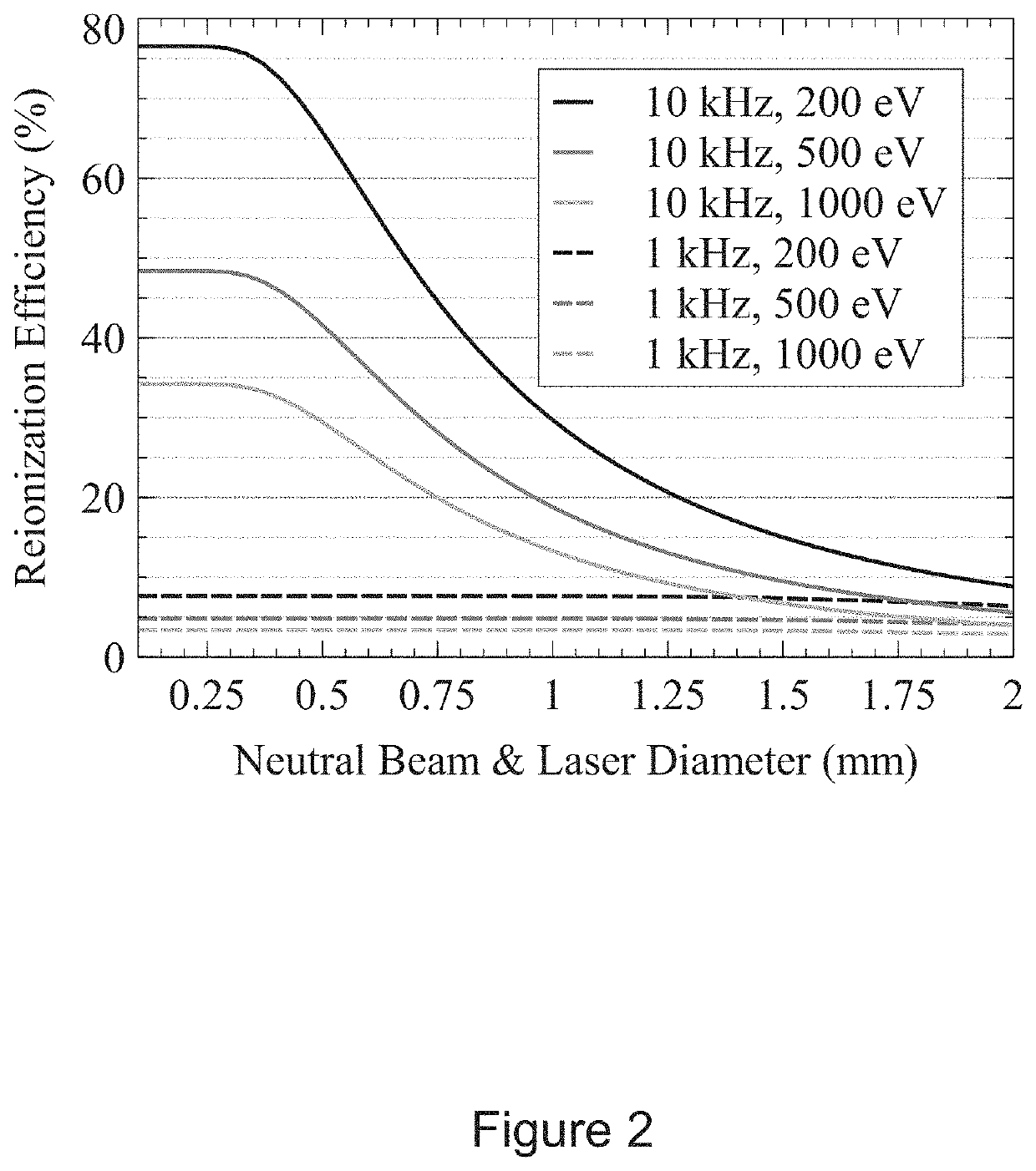
[0045]FIG. 2 shows the effects of the neutral beam and laser diameters relative to the reionization efficiency of the RIF for a mass 100 amu atom over a 1.5 m drift length with a saturation irradiance of 2 MW / cm2. The transit time of the atom, and therefore the efficiency, depends upon the decelerated ion energy, the drift length, and the atom mass (see different curves for each laser frequency).

[0046]FIG. 2 also shows the dramatically different sensitivity to neutral beam size between the two laser frequencies. This arises from the difference in irradiance between the two lasers: 0.25 MW / cm2 for the 10 kHz system and 3.61 MW / cm2 for the 1 kHz.

[0047]The 10 kHz system experiences a significant efficiency boost with smaller neutral beam diameters due to its lower irradiance, though this effect saturates below 0.4 mm.

[0048]In contrast, the 1 kHz system is hardly influenced by the neutral beam diameter because its irradiance is already high, but it is limited by a low repetition rate, w...


PUM


Abstract

A method of removing nuclear isobars from a mass spectrometric technique comprising directing ions, decelerating the ions, neutralizing a first portion of the ions, creating residual ions and a second portion of the ions, reionizing a selective portion of the ions, re-accelerating the selective reionized portion of ions, and directing the reionized portion of ions to a detector. An apparatus to remove nuclear isobars comprising a deceleration lens, an equipotential surface, an electron source to neutralize a portion of the ion beam, a deflector pair, a tunable resonance ionization laser for selective resonant reionization, and an acceleration lens.

Description

REFERENCE TO RELATED APPLICATION[0001]This application is a non-provisional of, and claims priority to and the benefits of, U.S. Provisional Patent Application No. 63 / 028,836 filed on May 22, 2020, the entirety of which is herein incorporated by reference.BACKGROUND[0002]This disclosure concerns a device and method to select an isotope / element of interest by removing nuclear isobars from mass spectrometric techniques—such as secondary ion mass spectrometry (SIMS), and coupled SIMS-accelerator mass spectrometry (AMS)—through the addition of a resonance ionization filter (RIF).[0003]The RIF allows for the discrimination of nuclear isobars (analytical interferences) in-situ, without requiring separation chemistry.[0004]This new device and method allow for maintaining the petrologic context of samples during analysis. For small (micrometer-sized) samples, there are no alternatives to this technique, since chemistry is not feasible.[0005]The RIF will perform ion beam neutralization follo...

Claims


Application Information

Patent Timeline
Patent Type & Authority Patents(United States)
IPC IPC(8): H01J49/00H01J49/06H01J49/40H01J49/32
CPCH01J49/0031H01J49/061H01J49/067H01J49/324H01J49/401H01J49/162
Inventor GROOPMAN, EVAN E.WILLINGHAM, DAVID G.
Owner THE UNITED STATES OF AMERICA AS REPRESENTED BY THE SECRETARY OF THE NAVY
Learn More