
Fan system and monitoring method for fan system

Active Publication Date: 2022-11-15
MIDASTEK MICROELECTRONICS
View PDF8 Cites 0 Cited by
  • Summary
  • Abstract
  • Description
  • Claims
  • Application Information

AI Technical Summary

Benefits of technology

The patent is about a fan system and a monitoring method that allows a controller to receive and convert operating raw data into operating state data. This results in a reduction of memory space requirement and allows for early warning notification signals. The technical effect of this patent is to improve the efficiency and monitoring capabilities of the fan system.

Problems solved by technology

However, fans are often regarded as components exhibiting low reliability.
If the fan is abnormal or fails, it will cause the apparatus to overheat and stop or be damaged.

Method used


Image

  • Fan system and monitoring method for fan system
  • Fan system and monitoring method for fan system
  • Fan system and monitoring method for fan system

Examples


first embodiment

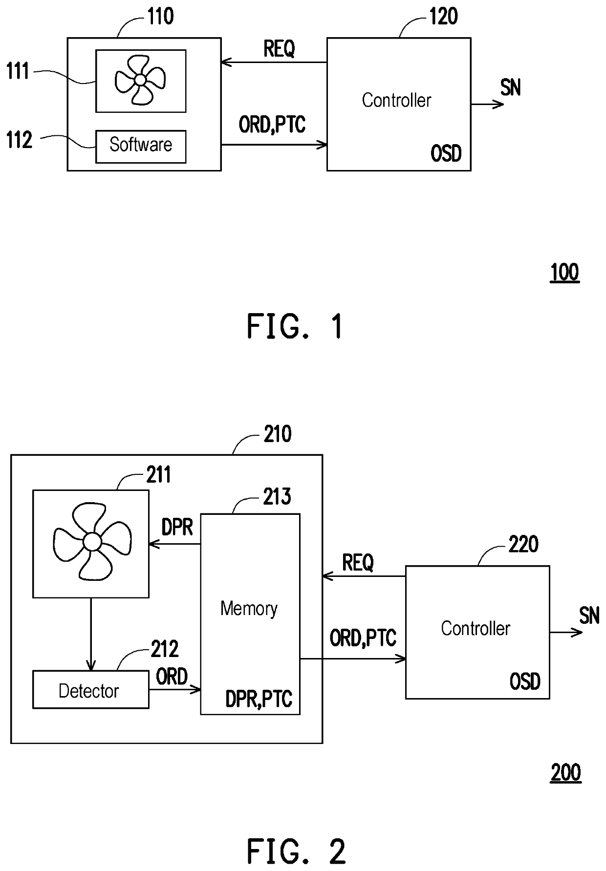
[0020]With reference to FIG. 1, FIG. 1 is a schematic diagram illustrating a fan system according to the disclosure. In this embodiment, the fan system 100 includes a fan device 110 and a controller 120. The fan device 110 includes a fan unit 111 and software 112. The fan unit 111 may be, for example, a cooling element that uses a motor to drive fan blades to achieve a cooling effect. The fan device 110 may communicate with the controller 120 through the software 112. To be specific, the software 112 may record operating raw data ORD of the fan device 110 during operation. The operating raw data ORD includes, for example, at least one of a driving current value, a driving voltage value, an ambient temperature value, and an operating time length of the fan device 110 during operation. The controller 120 may be, for example, an electronic device having a computing function. The controller 120 and the fan device 110 may communicate to each other by a wired communication method or a wir...

fourth embodiment

[0047]With reference to FIG. 9, FIG. 9 is a schematic diagram illustrating a fan system according to the disclosure. In this embodiment, a fan system 400 includes a fan device 410, a controller 420, and a monitoring terminal 430. The fan device 410 includes a fan unit 411 and software 412. The monitoring terminal 430 and the controller 420 may communicate to each other by a wired communication method or a wireless communication method known to a person having ordinary skill in the art. The cooperative operation of the fan device 410 and the controller 420 of this embodiment may be sufficiently taught by the embodiments of FIG. 1 to FIG. 8, so description thereof is not repeated herein. In this embodiment, the monitoring terminal 430 collects an early warning notification signal SN1 through the controller 420 and issues the early warning notification signal SN1. The user may repair or maintain the fan device 410 according to the early warning notification signal SN1 issued by the con...


PUM


Abstract

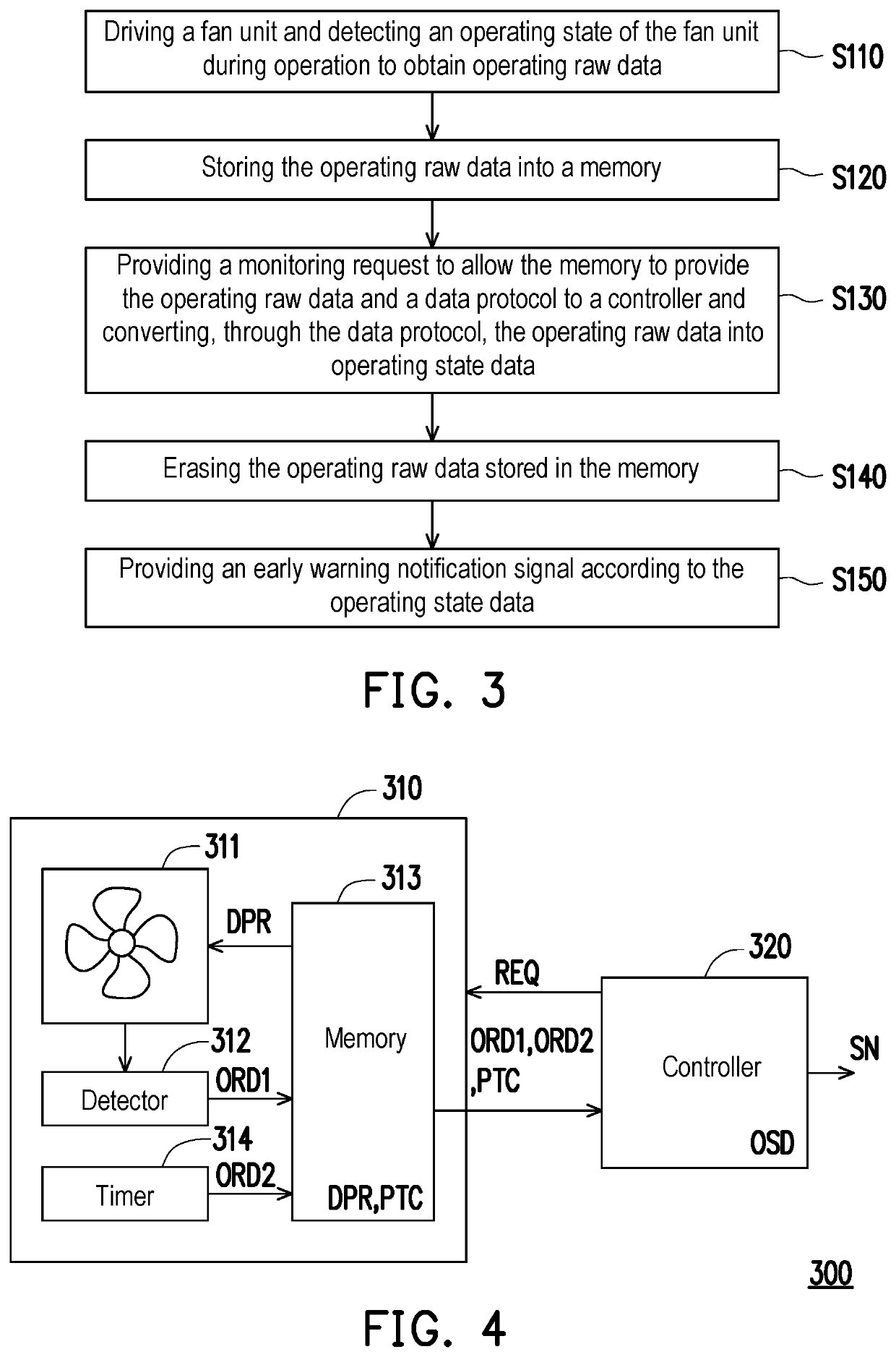
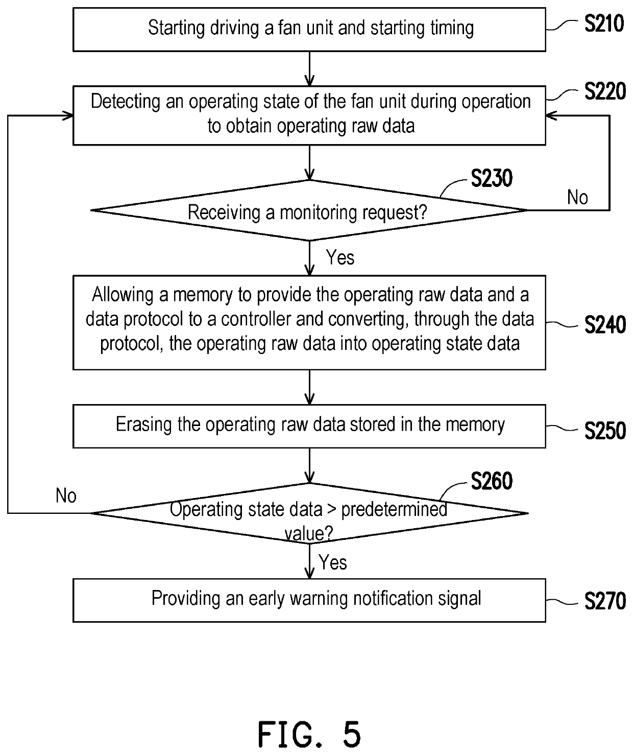
A fan system and a monitoring method are provided. The fan system includes a fan device and a controller. The fan device includes a fan unit, a detector, and a memory. The detector detects an operating state of the fan unit during operation to obtain operating raw data corresponding to the operating state. The memory records the operating raw data and stores a data protocol. The controller provides a monitoring request to allow the memory to provide the operating raw data and a data protocol to the controller, converts the operating raw data into operating state data through the data protocol, and provides an early warning notification signal according to the operating state data. When the operating raw data is provided to the controller, the operating raw data stored in the memory is erased.

Description

CROSS-REFERENCE TO RELATED APPLICATION[0001]This application claims the priority benefit of Taiwan application serial no. 110146848, filed on Dec. 15, 2021. The entirety of the above-mentioned patent application is hereby incorporated by reference herein and made a part of this specification.BACKGROUNDTechnical Field[0002]The disclosure relates to a fan system and a monitoring method for the fan system, and in particular, relates to a fan system and a monitoring method capable of providing an early warning notification according to an operating state of a fan.Description of Related Art[0003]Fans are used in most apparatuses (e.g., production equipment, personal computers, notebook computers, etc.) for cooling. An apparatus may run smoothly thanks to the cooling effect provided by the fan. However, fans are often regarded as components exhibiting low reliability. If the fan is abnormal or fails, it will cause the apparatus to overheat and stop or be damaged. Therefore, the fan needs ...

Claims


Application Information

Patent Timeline
IPC IPC(8): F04D27/02F04D27/00G05B19/042G05B19/048
CPCF04D27/001G05B19/048G05B19/0428F04D25/08F04D27/006F04D27/008G06F1/20F05D2260/80F04D25/0613G05B2219/24033G05B23/0224
Inventor TAN, CHUNG-PING
Owner MIDASTEK MICROELECTRONICS
Learn More