
Battery cell having welded battery cap

Active Publication Date: 2022-11-08
TESLA INC
View PDF19 Cites 0 Cited by
  • Summary
  • Abstract
  • Description
  • Claims
  • Application Information

AI Technical Summary

Benefits of technology

[0007]With the battery of the first embodiment, multiple benefits exist. Because the conductive top plate is constructed first and later welded to the can, damage caused to the jelly roll during manufacture is minimized. Further, the top insulator may be constructed with less strength, of a cheaper insulator and with a thinner profile, resulting in lesser cost. With the battery cap constructed according to the first embodiment, the battery has a lower profile than prior batteries, allowing more room for the jelly roll, a lower weight of the battery, and a greater battery capacity for a comparable volume and weight.

Problems solved by technology

Further, the lifetime of the batteries and the complexity of interconnection of the batteries within the array is also very important.
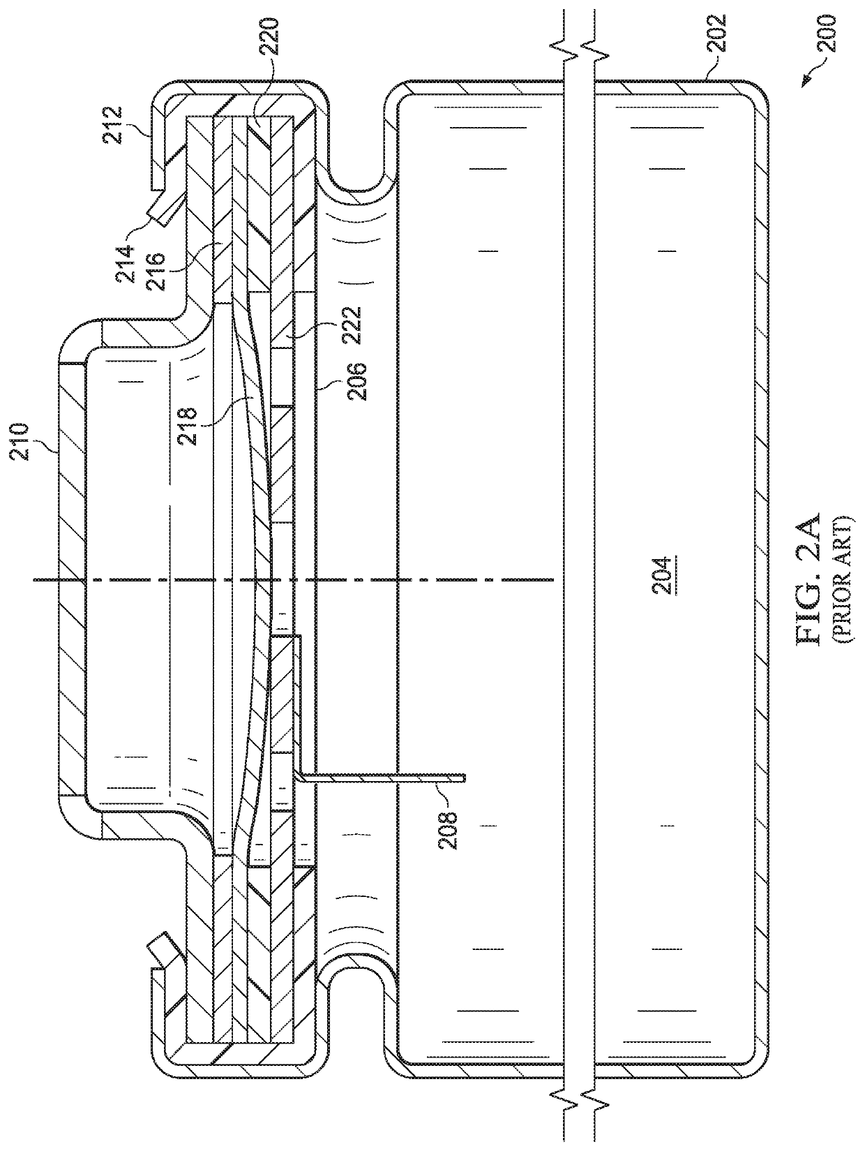
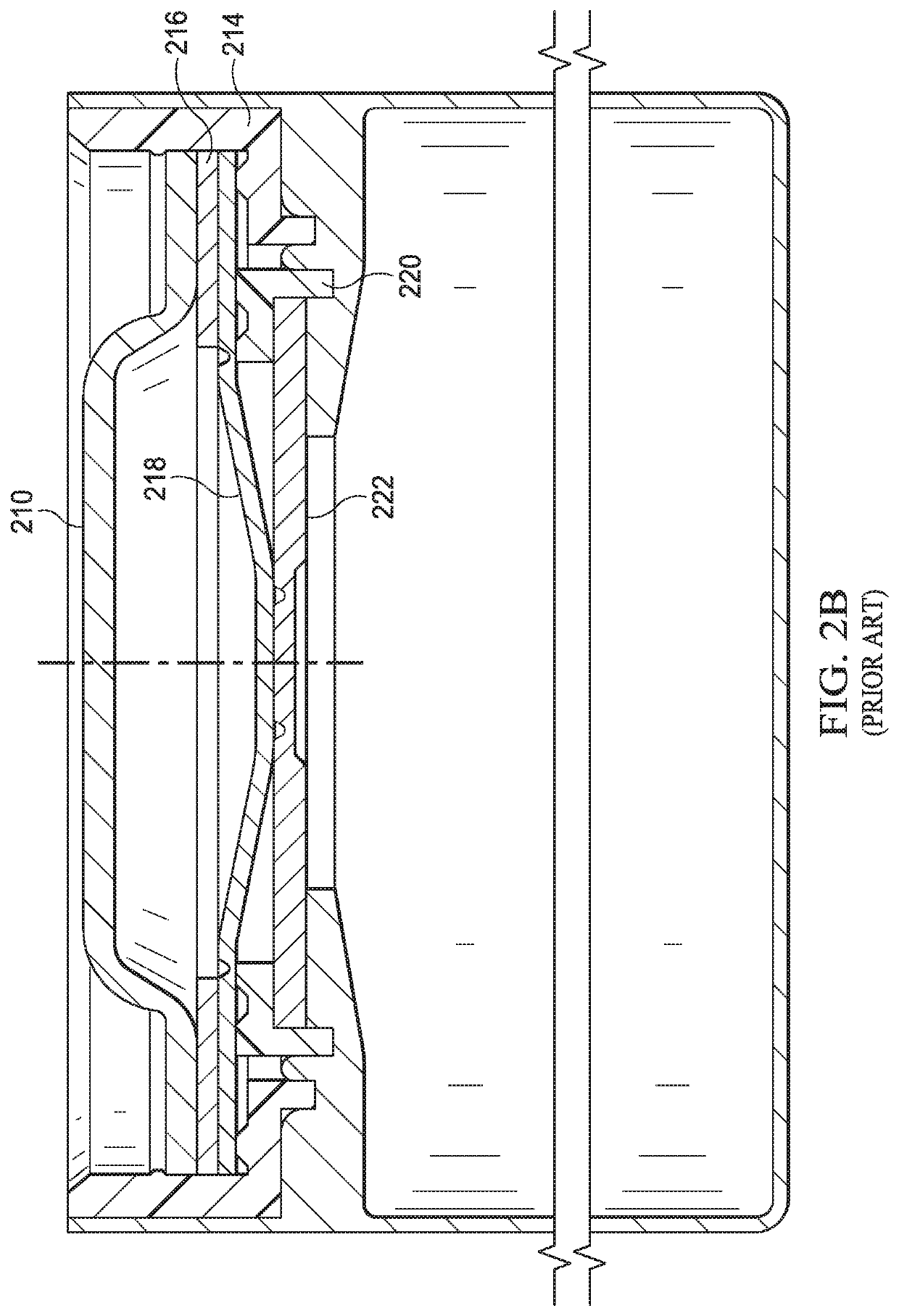
This structure is fairly simple but has a number of problems.
Crimping the battery cap to the can often damages the jelly roll.
Further, because the top insulator, which holds the jelly roll in place, is only held in place by the crimping structure, the top insulator only provides weak physical protection for the jelly roll and must be of a material that is fairly rigid, reducing volume for the jelly roll.
Because the jelly roll can expand with operating temperature, this weak physical protection can lead to premature failure of the battery.

Method used


Image

  • Battery cell having welded battery cap
  • Battery cell having welded battery cap
  • Battery cell having welded battery cap

Examples


Embodiment Construction

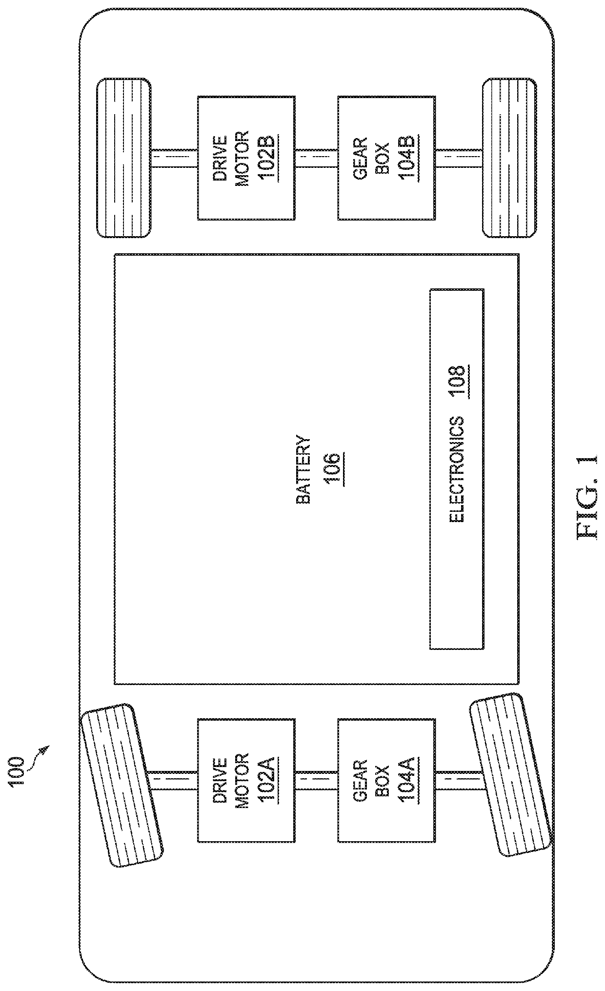
[0026]FIG. 1 illustrates the basic components of a battery powered electric vehicle (electric vehicle) 100. The electric vehicle 100 includes at least one drive motor (traction motor) 102A and / or 102B, at least one gear box 104A and / or 104B coupled to a corresponding drive motor 102A and / or 102B, a battery pack 106 and electronics 108 (including drive motor electronics). Generally, the battery pack provides electricity to the electronics 108 of the electric vehicle 100 and to propel the electric vehicle 100 using the drive motor 102A and / or 102B. The battery pack 106 includes an array of individual batteries constructed according to one or more embodiments of the present invention. The battery pack 106, in some embodiments, includes thousands of individual batteries.

[0027]The electric vehicle 100 includes a large number of other components that are not described herein but known to one or ordinary skill. While the construct of the electric vehicle 100 of FIG. 1 is shown to have four...


PUM

PropertyMeasurementUnit
conductiveaaaaaaaaaa
volumeaaaaaaaaaa
electrical polarityaaaaaaaaaa

Abstract

A battery includes a can, a jelly roll contained in the can, a top insulator contained in the can adjacent to and above the jelly roll, and a battery cap. The battery cap is welded to an inner surface of the can adjacent to and above the top insulator and includes an outer conductive ring, an insulator ring, and a conductive top plate, wherein the outer conductive ring, the insulator ring, and the conductive top plate are crimped together. The battery cap further includes a conductive rupture plate electrically connected to the conductive top plate and a cathode electrically connected to the conductive rupture plate and extending into the jelly roll. The battery may further include an opening in a central portion of the conductive top plate and a central portion of the conductive rupture plate cover welded upon the opening in the central portion of the conductive top plate.

Description

CROSS-REFERENCE TO RELATED APPLICATION[0001]The present U.S. Utility Patent Application claims priority pursuant to 35 U.S.C. §371 as U.S. National Phase Application of PCT / US2017 / 038973, entitled “BATTERY CELL HAVING WELDED BATTERY CAP”, filed 23 Jun. 2017, which claims priority pursuant to 35 U.S.C. §119(e) to U.S. Provisional Patent Application No. 62 / 353,664, entitled “BATTERY CELL HAVING WELDED BATTERY CAP’, filed 23 Jun. 2016, both of which are incorporated herein by reference in their entirety for all purposes.BACKGROUNDTechnical Field[0002]The present invention relates to batteries; and more particularly to the structure of single cell batteries that may be used in an array of batteries.Description of Related Art[0003]Rechargeable electric batteries have been known for some time and are used in a large number of devices including consumer electronics, vehicles, and a great number of other types of devices. In electric vehicles (or hybrid electric vehicles), for example, thou...

Claims


Application Information

Patent Timeline
Patent Type & Authority Patents(United States)
IPC IPC(8): H01M50/147H01M10/04H01M50/155H01M50/166H01M50/169H01M50/578H01M50/342H01M50/10H01M50/56H01M50/107
CPCH01M50/147H01M10/0431H01M50/155H01M50/166H01M50/169H01M50/3425H01M50/578H01M50/10H01M50/56H01M2220/20H01M50/107Y02E60/10Y02P70/50H01M10/0422
Inventor MASUMOTO, KENJINMILLE, CHRISTOPHE
Owner TESLA INC
Learn More