Eureka AIR delivers breakthrough ideas for toughest innovation challenges, trusted by R&D personnel around the world.

Power supply system

a power supply system and power supply technology, applied in the direction of capacitor propulsion, dynamo-electric converter control, instruments, etc., can solve the problem of not being able to appropriately determine the existence of welding of contactors, and achieve the effect of reducing the loss of the power supply system overall

Active Publication Date: 2022-11-01
HONDA MOTOR CO LTD
View PDF3 Cites 1 Cited by
  • Summary
  • Abstract
  • Description
  • Claims
  • Application Information

AI Technical Summary

Benefits of technology

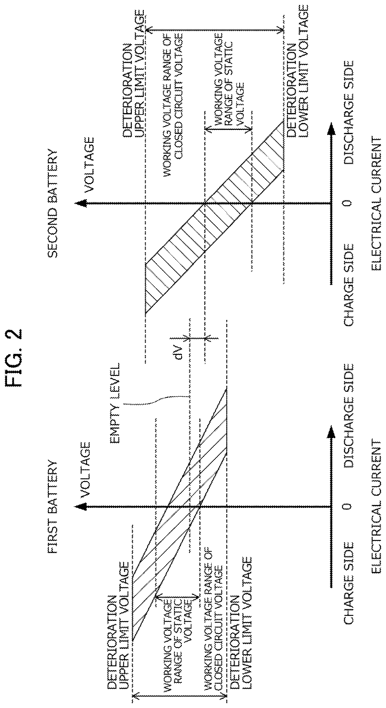
The present invention provides a power supply system that can appropriately determine the existence of failure of contactors in electric energy storage devices. The system uses two electric energy storage devices connected via contactors, and a controller that can detect if there is a failure in a contactor by measuring the voltage at the contactor. The system also includes a voltage converter that can output more electric power from the second energy storage device than the first energy storage device when the static voltage of the first energy storage device is higher than a predetermined level. This ensures that the potential difference between the two energy storage devices remains high enough to determine the failure of the contactors during system interruption. The power supply system is designed to reduce loss in power supply overall and appropriately determine the failure of the contactors.

Problems solved by technology

For this reason, with the capacitor welding determination method shown in Japanese Unexamined Patent Application, Publication No. 2007-244123, it may not be possible to appropriately determine the existence of welding of a contactor.

Method used


Image

  • Power supply system
  • Power supply system
  • Power supply system

Examples


Embodiment Construction

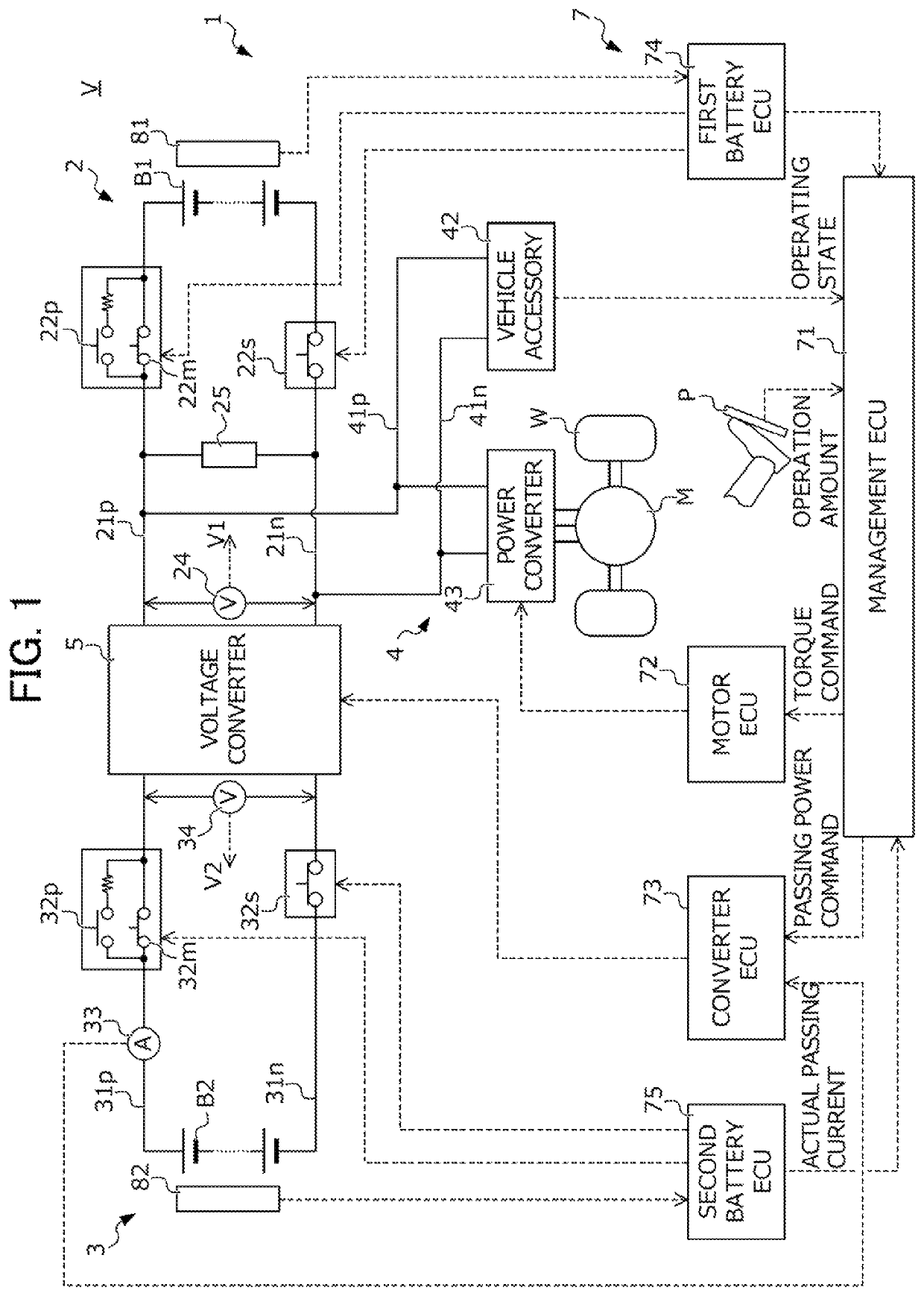
[0024]Hereinafter, an embodiment of the present invention will be explained while referencing the drawings. FIG. 1 is a view showing the configuration of an electric vehicle V (hereinafter simply referred as “vehicle”) equipped with a power supply system 1 according to the present embodiment.

[0025]The vehicle V includes: a drive wheel W; a drive motor M coupled to this drive wheel W; and a power supply system 1 which performs transfer of electric power between this drive motor M and the first battery B1 and second battery B2 described later. It should be noted that the present embodiment explains an example in which the vehicle V accelerates / decelerates by the electric power generated by the drive motor M mainly; however, the present invention is not limited thereto. The vehicle V may be established as a so-called hybrid vehicle equipped with the drive motor M and an engine as power generation sources. In addition, the present embodiment explains as an example the power supply syste...


PUM


Abstract

A power supply system 1 includes: first power lines (21p, 21n) to which a first battery (B1) is connected; second power lines (31p, 31n) to which a second battery (B2) is connected; a voltage converter (5) which converts voltage; a power converter which converts electric power; a management ECU (71) and converter ECU (73) which operates the voltage converter (5); a smoothing capacitor connected to the first power lines (21p, 21n); and a motor ECU (72) which executes system interruption processing of determining the existence of failure of the contactors (22m, 22s, 32m, 32s) based on a change in voltage of the smoothing capacitor. The management ECU (71) and converter ECU (73) operate the voltage converter (5) so that a state in which the static voltage of the first battery (B1) is higher by at least the determination potential difference than the static voltage of the second battery (B2).

Description

[0001]This application is based on and claims the benefit of priority from Japanese Patent Application No. 2019-105874, filed on 6 Jun. 2019, the content of which is incorporated herein by reference.BACKGROUND OF THE INVENTIONField of the Invention[0002]The present invention relates to a power supply system. In more detail, it relates to a power supply system which includes a first power line to which a first electric energy storage device is connected via a first contactor, and a second power line to which a second electric energy storage device is connected via a second contactor, and determines the existence of failure of the first and second contactors during system interruption.Related Art[0003]In recent years, the development has been active of electric vehicles such as electric transport equipment equipped with a drive motor as a power generation source, and hybrid vehicles equipped with a drive motor and internal combustion engine as power generation sources. In such electri...

Claims


Application Information

Patent Timeline
Patent Type & Authority Patents(United States)
IPC IPC(8): H02P1/00B60L3/12H02M3/158G01R31/66G01R31/00B60L50/40
CPCB60L3/12B60L50/40G01R31/006G01R31/66H02M3/158B60L2210/10B60L3/00B60L3/0046B60R16/02B60L50/60B60L58/20B60L1/00B60L3/0023H02M1/007Y02T10/70
Inventor TAGAYA, NAOTOOGUMA, HIROKAZUSAKAMOTO, HIROKISONE, TOSHIHIROSUZUKI, KENTA
Owner HONDA MOTOR CO LTD
Why Eureka
Eureka Blog
Learn More