
Light emitting device

a technology of light emitting device and light source, which is applied in the direction of semiconductor devices for light sources, light source combinations, lighting and heating apparatus, etc., can solve the problems of poor vision, tired human body, and inability to perform physical activities

Active Publication Date: 2022-09-13
SEOUL SEMICONDUCTOR
View PDF15 Cites 0 Cited by
  • Summary
  • Abstract
  • Description
  • Claims
  • Application Information

AI Technical Summary

Benefits of technology

[0010]Light emitting devices constructed according to exemplary embodiments of the invention and lighting apparatuses including the same are capable of preventing the human lens or retina from being damaged by light in an abnormal blue region or may alleviate the damage therefrom.

Problems solved by technology

In the daytime, physical activities are performed under strong sunlight, but melatonin hormone is secreted in the evening and lowers pulse rate, body temperature, and blood pressure, which gets a human body tired and helps human to fall asleep.
However, in modern society, most people do not perform physical activities under sunlight, and mainly work in indoors, such as homes and offices.
Human lenses that have adapted to the solar spectrum may be damaged by light in the unusually strong blue wavelength region, which may result in poor vision.
In addition, when retinal cells are exposed to excessive energy in the blue region, abnormal signals may be transmitted to the brain, which may negatively affect the body's circadian rhythm by abnormally producing or inhibiting hormones, such as cortisol and melatonin.

Method used


Image

  • Light emitting device
  • Light emitting device
  • Light emitting device

Examples


Embodiment Construction

[0052]In the following description, for the purposes of explanation, numerous specific details are set forth in order to provide a thorough understanding of various exemplary embodiments or implementations of the invention. As used herein “embodiments” and “implementations” are interchangeable words that are non-limiting examples of devices or methods employing one or more of the inventive concepts disclosed herein. It is apparent, however, that various exemplary embodiments may be practiced without these specific details or with one or more equivalent arrangements. In other instances, well-known structures and devices are shown in block diagram form in order to avoid unnecessarily obscuring various exemplary embodiments. Further, various exemplary embodiments may be different, but do not have to be exclusive. For example, specific shapes, configurations, and characteristics of an exemplary embodiment may be used or implemented in another exemplary embodiment without departing from ...


PUM

PropertyMeasurementUnit
color temperatureaaaaaaaaaa

Abstract

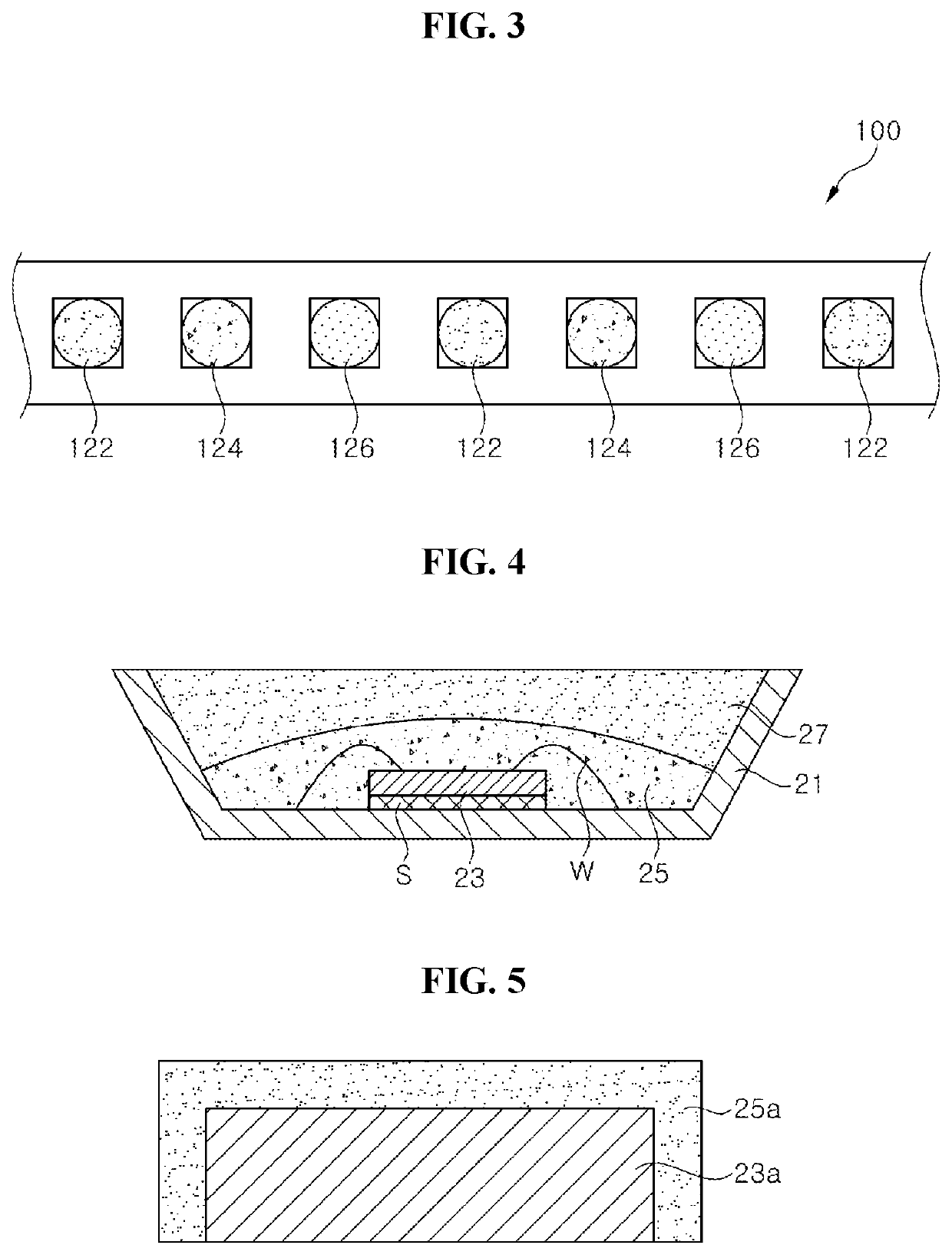
A light emitting device including at least one first light emitting unit including an ultraviolet or violet light emitting diode chip and a first wavelength converter, at least one second light emitting unit including an ultraviolet or violet light emitting diode chip and a second wavelength converter, and at least one third light emitting unit including an ultraviolet or violet light emitting diode chip and a third wavelength converter, in which color coordinates of the first light emitting unit, the second light emitting unit, and the third light emitting unit define a triangular region in a CIE-1931 coordinate system, the triangular region including at least a portion of the Plankian locus, and a maximum color temperature of the Plankian locus included in the triangular region is 5000K or higher, and a minimum color temperature of the Plankian locus included in the triangular region is 3000K or lower.

Description

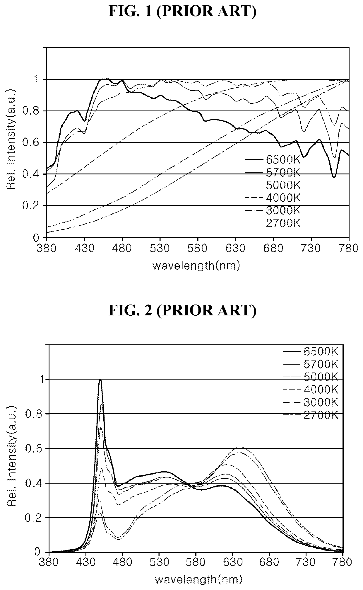
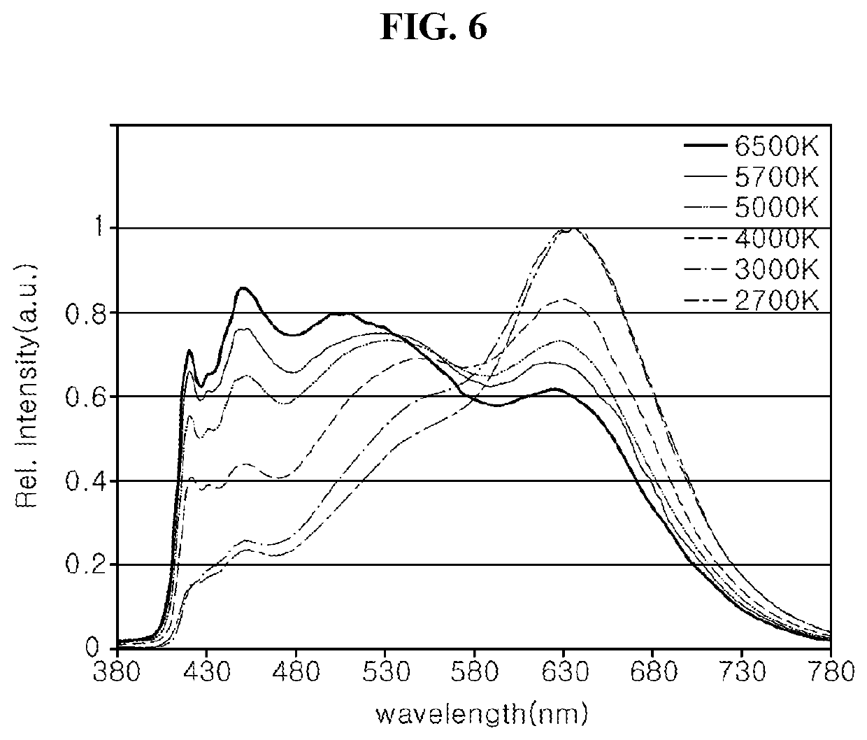
CROSS-REFERENCE TO RELATED APPLICATION[0001]This application claims the benefit of U.S. Provisional Application No. 62 / 730,098, filed Sep. 12, 2018, which is hereby incorporated by reference for all purposes as if fully se forth herein.BACKGROUNDField[0002]Exemplary embodiments of the invention relate generally to a light emitting device and, more specifically, to a light emitting device capable of changing a spectral power distribution thereof to correspond to a spectral power distribution of sunlight.Discussion of the Background[0003]Most living organisms have been adapted to work in accordance with changes in sunlight. A human body has also been adapted to sunlight for a long period time. As such, the circadian rhythm of a human being changes in accordance with the change of sunlight. Especially in the morning, cortisol hormone is secreted in the human body under bright sunlight. Cortisol hormone allows more blood to be supplied to each organ of the body to counteract external st...

Claims


Application Information

Patent Timeline
Patent Type & Authority Patents(United States)
IPC IPC(8): H01L33/50H01L25/075H05B45/10
CPCH01L33/504H01L25/0753H05B45/10F21K9/64F21V9/40H05B45/20F21Y2115/10H01L25/13F21Y2113/13F21K9/00F21Y2105/16F21Y2103/10
Inventor HAN, BO YONG
Owner SEOUL SEMICONDUCTOR
Learn More