
Transparent multilayer structure for thermal management

Active Publication Date: 2022-09-13
COVESTRO DEUTSCHLAND AG
View PDF83 Cites 0 Cited by
  • Summary
  • Abstract
  • Description
  • Claims
  • Application Information

AI Technical Summary

Benefits of technology

The patent is about a new way to make a layered structure that helps to keep electronic devices cool. The researchers found that arranging the layers of metal and polycarbonate in a specific way can reduce the temperature inside the device. Surprisingly, using special absorbers to soak up infrared light also helps to keep the device cool. The patent also suggests that protective layers on top of the device don't interfere with the cooling effect. Additionally, the researchers found that adding carbon black to the layered structure doesn't make a difference, and that other substances can also be used instead of carbon black. Overall, the patent provides a new way to make electronic devices cooler and more efficient.

Problems solved by technology

However, absorption of the IR radiation results in significant heating of the thermoplastic materials, such that the thermoplastic materials themselves can in turn release heat by convection, radiation or thermal conduction to the respective interior.
System solutions for glass are not directly applicable to polycarbonate since the layer construction is unsuitable for polycarbonate owing to its distinctly lower barrier to oxygen and moisture by comparison with glass.
Although such multilayer articles have high IR reflectivity, they show inadequate optical properties, for example a metallic surface gloss which is undesirable for many applications, especially for glazing elements.
Moreover, weathering stability in the case of this construction is not assured.

Method used


Image

  • Transparent multilayer structure for thermal management

Examples


example 1

Comparative Example

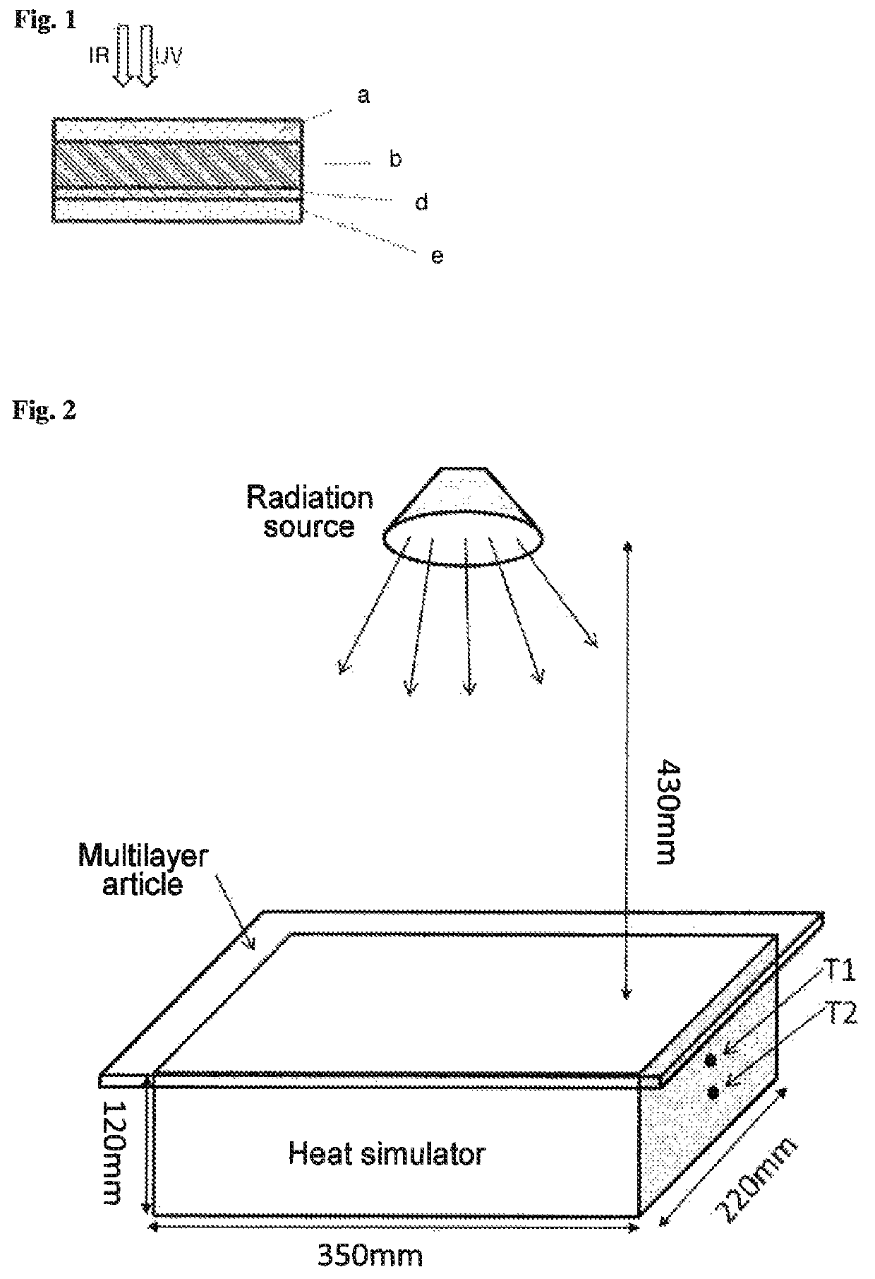
[0241]The heat simulator box was covered with a 4 mm-thick injection-molded polycarbonate sheet of substrate 1.

example 2

Comparative Example

[0242]The heat simulator box was covered with a 4 mm-thick injection-molded polycarbonate sheet of substrate 2.

example 3

Comparative Example

[0243]The heat simulator box was covered with a multilayer article composed of a 4 mm-thick layer of injection-molded substrate 2 and a layer sequence in the form of F1. The metal-containing foil was thus applied to the top side of substrate 2. “Top side” (i.e. “top”) here and hereinafter means the side facing toward the radiation source. The metal layer was thus laminated onto substrate 2 and hence enclosed between the carrier film of F1 and a layer of substrate 2.


PUM

PropertyMeasurementUnit
Fractionaaaaaaaaaa
Fractionaaaaaaaaaa
Fractionaaaaaaaaaa

Abstract

The invention relates to transparent multilayer structures and glazings or glazing elements comprising said multilayer structures, which are suitable for screening an indoor space from a radiation source, comprising, in this order a) optionally a protective layer a, b) a substrate layer based on a thermoplastic polymer, especially an aromatic polycarbonate, having a luminous transmittance in the range of 380 to 780 nm of at least 0.3%, determined at a layer thickness of 4 mm according to DIN ISO 13468-2:2006 (D65, 10°), and a TDS value of less than 40%, determined according to ISO 13837:2008 at a layer thickness of 4 mm, the substrate layer containing at least 0.001 wt. % of an IR absorber different from carbon black, c) if necessary, another layer c based on a thermoplastic polymer with a maximum thickness of 600 μm, d) at least one metal layer d, containing at least one element selected from the group including Ag, Al, Au, Pt, Fe, Cr, Sn, In, Ti, Pd, Nb, Cu, V or their alloys, the sum of thicknesses of all metal layers being 1 nm to not more than 30 nm, and e) optionally a protective layer e, at least 60% of the substrate layer b being covered by metal layer d, the layers following layer d, including the protective layer e, when added up, having a thickness of not more than 100 nm and the metal layer being applied to the side of the substrate layer b designed to be on the face of the multilayer structure facing away from the radiation source.

Description

CROSS-REFERENCE TO RELATED APPLICATIONS[0001]This application is a national stage application (under 35 U.S.C. § 371) of PCT / EP2017 / 079371, filed Nov. 16, 2017, which claims benefit of European Application No. 16199355.5, filed Nov. 17, 2016, both of which are incorporated herein by reference in their entirety.[0002]The invention relates to a transparent multilayer article suitable for shielding a three-dimensional volume from a radiation source, especially from IR radiation. The invention also relates to glazing and glazing elements, especially roof modules, comprising such a multilayer article.BACKGROUND OF THE INVENTION[0003]Component parts based on thermoplastic material for use in the automotive sector offer many advantages over conventional materials, such as glass for example. These include, for example, elevated fracture resistance and / or a weight saving, which in the case of automobiles allow greater occupant safety in road traffic accidents and lower fuel consumption. Fina...

Claims


Application Information

Patent Timeline
IPC IPC(8): B60J3/00B32B27/08B32B27/20B32B27/36B32B7/027B32B7/12B60J1/00
CPCB60J3/007B32B7/027B32B7/12B32B27/08B32B27/20B32B27/365B60J1/00B32B2250/04B32B2255/10B32B2255/205B32B2255/26B32B2264/10B32B2307/30B32B2307/412B32B2605/006B60J1/002B32B15/08B32B15/082B32B15/085B32B15/09B32B15/095B32B15/18B32B15/20B32B27/18B32B27/30B32B27/32B32B27/40B32B1/00B32B2255/24B32B2307/584B32B2307/718B32B27/36
Inventor MEYER, ALEXANDEROSER, RAFAELHINZMANN, DIRKKUHLMANN, TIMO
Owner COVESTRO DEUTSCHLAND AG
Learn More