Control system for hybrid vehicle

a control system and hybrid technology, applied in the direction of couplings, slip couplings, transportation and packaging, etc., can solve the problems of unfavorable actuation of the clutch, the clutch may be shifted undesirably, and the response delay of the engagement device may be caused inevitably

Active Publication Date: 2022-06-28
TOYOTA JIDOSHA KK
View PDF6 Cites 0 Cited by
  • Summary
  • Abstract
  • Description
  • Claims
  • Application Information

AI Technical Summary

Benefits of technology

[0014]In a non-limiting embodiment, the controller may be further configured to execute the transient slip control in such a manner that the torque transmitting capacity of the first clutch is increased with respect to an ideal torque transmitting capacity of the first clutch given that the first clutch is engaged partially in an ideal condition in which the speed of the engine will not be changed.
[0016]Thus, according to the exemplary embodiment of the present disclosure, the transient slip control is executed to prevent an overheating of the first clutch engaged partially to launch the hybrid vehicle, when the temperature of the first clutch reaches the predetermined level. In this situation, if the speed of the engine is changed undesirably as a result of executing the transient slip control, the speed of the engine is corrected by controlling the correction torque of the first motor by a feedback method. For example, in the case that the speed of the engine is raised temporarily as indicated in FIG. 1, such rise in the speed of the engine is suppressed by generating a negative correction torque by the first motor. By contrast, in the case that the speed of the engine is reduced temporarily as indicated in FIG. 1, such reduction in the speed of the engine is suppressed by generating a positive correction torque by the first motor. According to the exemplary embodiment of the present disclosure, the thermal damage to the first clutch may be limited when launching the hybrid vehicle, and the hybrid vehicle may be launched smoothly without generating shocks.
[0017]During execution of the transient slip control, drive force to propel the hybrid vehicle and acceleration of the hybrid vehicle may be changed as a result of correcting the speed of the engine by the correction torque of the first motor during execution of the transient slip control of the clutches. In order to suppress such change in the drive force and the acceleration, according to the exemplary embodiment of the present disclosure, the second motor generates the counter torque against the correction torque of the first motor. According to the exemplary embodiment of the present disclosure, therefore, overheating of the first clutch may be prevented when launching the hybrid vehicle, and the hybrid vehicle is allowed to launch smoothly without shock. In other words, the first clutch can be protected while improving driving comfort when launching the hybrid vehicle.
[0018]The second motor is mainly used under high load to launch and accelerate the hybrid vehicle by generating the positive torque, therefore, the positive torque of the second motor may be restricted when reaches an upper limit. However, the second motor is allowed to generate the negative torque without restriction to counteract to the positive correction torque of the first motor. Therefore, the controller executes the transient slip control in such a manner that the torque transmitting capacity of the first clutch is increased with respect to the ideal torque transmitting capacity. In this case, as indicated in FIG. 2, the speed of the engine is reduced from the target speed during execution of the transient slip control. Consequently, the second motor is allowed to generate the counter torque in the negative direction to counter act to the positive correction torque generated by the first motor. In this case, therefore, change in the drive force to propel the hybrid vehicle and change in the acceleration of the hybrid vehicle resulting from correcting the speed of the engine by the first motor may be suppressed certainly by generating the negative torque by the second motor without restriction. For this reason, the thermal damage to the first clutch may be limited without shock.
[0019]In addition, after engaging the first clutch completely during execution of the friction start, the controller continues the friction start by causing the second clutch to slip. According to the exemplary embodiment of the present disclosure, therefore, the hybrid vehicle is allowed to be launched smoothly by the friction start without damaging the first clutch.

Problems solved by technology

Therefore, a response delay of those engagement devices may be caused inevitably.
For this reason, a timing of switching engagement states of the clutches may be shifted undesirably, and actuation amounts of the of the clutches may be changed undesirably.
Thus, according to the conventional art, a timing of switching engagement states of the clutches may be shifted undesirably and actuation amounts of the of the clutches may be changed undesirably due to response delay of the hydraulically actuated clutches, during execution of so-called a “transient slip control”.
For this reason, a rotational speed of the prime mover and an acceleration of the vehicle may be changed temporarily thereby causing a shock.
In addition, a driver may feel uncomfortable feeling.
The second motor is mainly used under high load to launch and accelerate the hybrid vehicle by generating the positive torque, therefore, the positive torque of the second motor may be restricted when reaches an upper limit.
For this reason, the thermal damage to the first clutch may be limited without shock.
In addition, after engaging the first clutch completely during execution of the friction start, the controller continues the friction start by causing the second clutch to slip.

Method used


Image

  • Control system for hybrid vehicle
  • Control system for hybrid vehicle
  • Control system for hybrid vehicle

Examples


Embodiment Construction

)

[0029]Preferred embodiments of the present disclosure will now be explained with reference to the accompanying drawings.

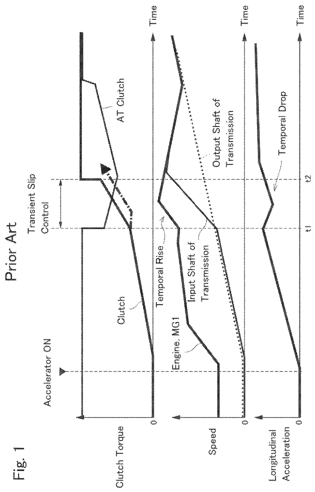
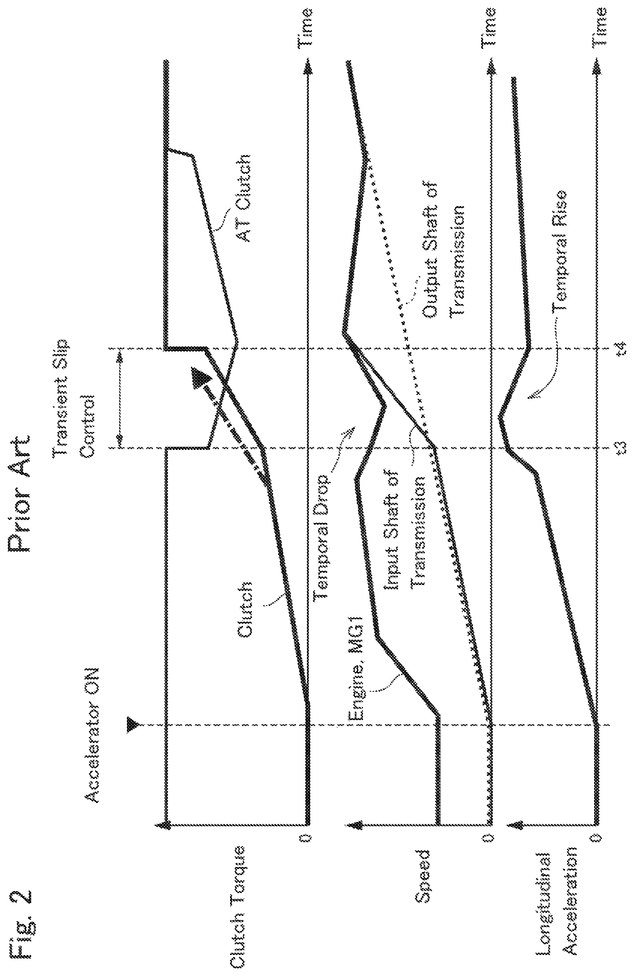
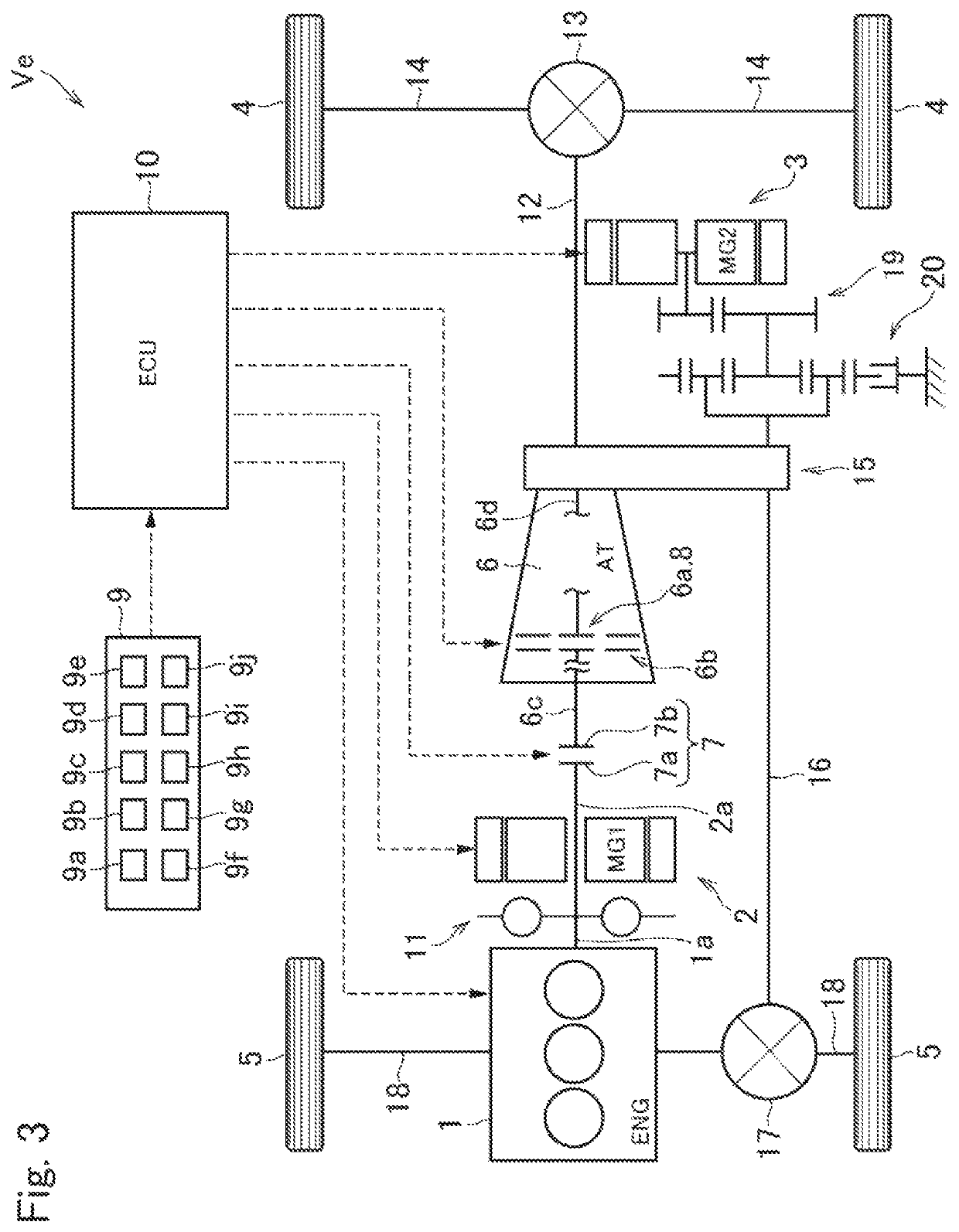
[0030]Referring now to FIG. 3, there is shown one example of a drive system and a control system of a hybrid vehicle (as will be simply called the “vehicle” hereinafter) Ve to which the control system according to the embodiment of the present disclosure is applied. A prime mover of the vehicle Ve includes an engine 1 (referred to as “ENG” in FIG. 3), a first motor (referred to as “MG1” in FIG. 3) 2, and a second motor (referred to as “MG2” in FIG. 3) 3. In the vehicle Ve, the first motor 2 is connected to the engine 1 so that an output torque of the first motor 2 is delivered to a pair of front wheels 5 and a pair of rear wheels 4 through an automatic transmission (referred to as “AT” in FIG. 3) 6. An output torque of the second motor 3 is delivered directly to the front wheels 5 and the rear wheels 4 without passing through the automatic transmission (as will be...


PUM


Abstract

A control system for a hybrid vehicle configured to limit a thermal damage to a starting clutch without generating a shock. The control system is applied to a vehicle in which a prime mover includes an engine, a first motor, and a second motor. In the vehicle, the first motor is connected to the engine, and a first clutch and a second clutch are disposed between the engine and drive wheels. A controller executes a transient slip control to cause the second clutch to slip while bringing the slipping first clutch into complete engagement if a temperature of the first clutch is high. If an engine speed is changed during execution of the transient slip control, the first motor generates a collection torque to suppress the change in the engine speed.

Description

CROSS REFERENCE TO RELATED APPLICATIONS[0001]The present disclosure claims the benefit of Japanese Patent Application No. 2018-244068 filed on Dec. 27, 2018 with the Japanese Patent Office, the disclosure of which are incorporated herein by reference in its entirety.BACKGROUNDField of the Disclosure[0002]Embodiments of the present disclosure relate to the art of a control system for a hybrid vehicle in which a prime mover includes an engine and a motor, and in which an output torque of the engine is transmitted through a friction clutch as a starting clutch.Discussion of the Related Art[0003]In conventional vehicles having an automatic transmission to transmit power of an engine to drive wheels, a torque converter has been used to launch the vehicle. Instead, in recent years, a friction clutch has also been used to launch the vehicle quickly and to improve power transmission efficiency. One example of such vehicle having the starting clutch is described in PCT publication WO2012 / 059...

Claims


Application Information

Patent Timeline
Patent Type & Authority Patents(United States)
IPC IPC(8): B60W20/40B60W10/02F16D7/02
CPCB60W20/40B60W10/02F16D7/02B60W2510/025B60W2710/026B60W10/06B60W10/08B60W30/18027B60W20/10B60W2510/0638B60W2510/083B60K2006/4808B60K2006/4825B60K6/448B60W20/15B60W30/186B60W2510/0291B60W2710/021B60W2710/083B60K2006/4833B60K6/48Y02T10/62
Inventor MIZUNO, JUNYAWATANABE, HIDEOTOMITA, TOSHIYUKIKONDO, MASAMI
Owner TOYOTA JIDOSHA KK
Why Eureka
Try Eureka