
Substrate-transferred stacked optical coatings

a technology of optical coatings and substrates, applied in the direction of polycrystalline material growth, after-treatment details, instruments, etc., to achieve the effects of reducing overall optical losses, improving the position dependence of coating optical properties, and high mechanical quality

Active Publication Date: 2022-06-21
THORLABS INC
View PDF10 Cites 0 Cited by
  • Summary
  • Abstract
  • Description
  • Claims
  • Application Information

AI Technical Summary

Benefits of technology

This patent is about a way to make optical coatings that can bend light better and have less optical loss. It uses high-quality crystalline materials to make layers that can help to reduce the impact of defects on the surface of the coatings. This can make the coatings perform better and more consistently. The patent also describes a process where layers of material are stacked on top of each other to make a more complete coating, which can help to improve the overall quality of the coating.

Problems solved by technology

However, a monocrystalline material does not contain grain boundaries and defects associated with said boundaries, separating neighboring crystallites of varying orientation in a polycrystalline sample.

Method used


Image

  • Substrate-transferred stacked optical coatings
  • Substrate-transferred stacked optical coatings
  • Substrate-transferred stacked optical coatings

Examples


Embodiment Construction

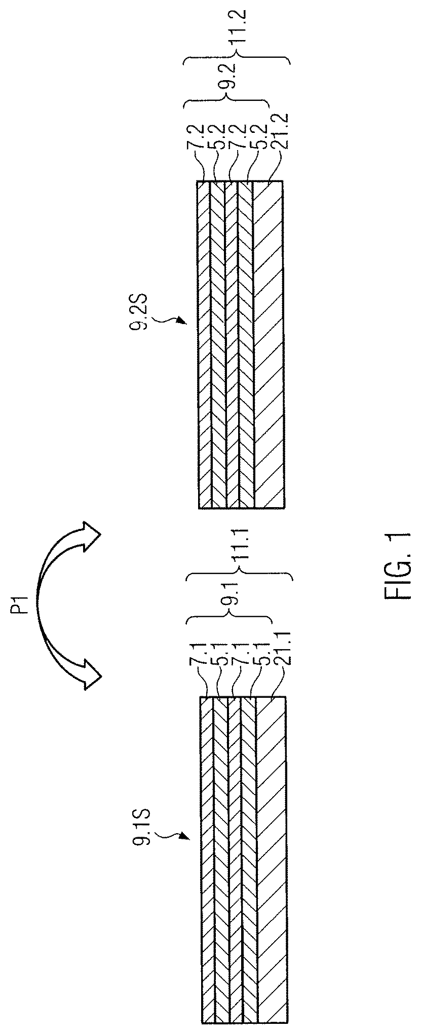
[0047]FIG. 1 illustrates a side view of an optical coating 9.1 provided on a host substrate 21.1 which form a base coating structure 11.1. The optical coating 9.1 may be denoted as a first optical coating and the host substrate 21.1 may be denoted as a first host substrate. The optical coating 9.1 may comprise layers 5.1 and 7.1. In an oversimplified schematic drawing the optical coating 9.1 is illustrated having only four layers 5.1, 7.1, respectively, provided in an alternating way. It should be understood, however, that the coating 9.1 typically comprises many more layers. The maximum reflectivity of the coating may be determined by the refractive index contrast of the individual layers, the total number of layers, as well as the refractive index of the substrate—asymptotically approaching a reflectivity of 100%. The number of layers for the present example may be about 40 pairs of layers, i.e. 80 total layers, but other numbers of layers such as 100-120 total layers may be used ...


PUM

PropertyMeasurementUnit
thicknessaaaaaaaaaa
wavelengthsaaaaaaaaaa

Abstract

A method for manufacturing substrate-transferred optical coatings, comprising: a) providing a first optical coating on a first host substrate as a base coating structure; b) providing a second optical coating on a second host substrate; c) bonding the optical coating of the base coating structure to the second optical coating, thereby obtaining one combined coating; d) detaching one of the first and the second host substrates from the combined coating; determining if the combined coating fulfills a predetermined condition; e) if the result of the determining step is negative, taking the combined coating together with the remaining host substrate as the base coating structure to be processed next and continuing with step b); f) if the result of the determining step is positive, providing an optical substrate and bonding the optical substrate to the combined coating; g) removing the other one of the first and the second host substrate.

Description

FIELD OF THE PRESENT DISCLOSURE[0001]The present disclosure relates to a method for manufacturing substrate-transferred stacked optical coatings.BACKGROUND OF THE PRESENT DISCLOSURE[0002]Highly reflective optical interference coatings are indispensable tools for modern scientific and industrial efforts. Systems with ultralow optical losses, namely parts-per-million, ppm, levels of scatter and absorption, were originally developed for the construction of ring-laser gyroscopes in the late 1970s, cf. U.S. Pat. No. 4,142,958. As an outcome of this, ion-beam sputtering, IBS, has been established as the gold standard process technology for generating ultralow-loss reflectors in the visible and near infrared, NIR. Typically, such multilayers consist of alternating layers of amorphous metal-oxides, most commonly high index Ta2O5, tantala, and low index SiO2, silica, thin films, finding application in narrow-linewidth laser systems for optical atomic clocks, gravitational wave detectors, cav...

Claims


Application Information

Patent Timeline
Patent Type & Authority Patents(United States)
IPC IPC(8): C30B33/06C30B23/02G02B1/02C30B29/68G02B5/08C30B29/40
CPCC30B33/06C30B23/02C30B29/40C30B29/68G02B1/02G02B5/0833
Inventor COLE, GARRETTDEUTSCH, CHRISTOPH
Owner THORLABS INC
Learn More