
Catalytic reactor

a catalytic reactor and apparatus technology, applied in the direction of physical/chemical process catalysts, metal/metal-oxide/metal-hydroxide catalysts, separation processes, etc., can solve the problem of limited heat to be conducted inward from the external wall or the reactor housing, and achieve the effect of improving the performance of the catalytic reactor, promoting higher conversion of reactants, and efficient supply

Active Publication Date: 2022-05-10
PRECISION COMBUSTION
View PDF20 Cites 0 Cited by
  • Summary
  • Abstract
  • Description
  • Claims
  • Application Information

AI Technical Summary

Benefits of technology

This invention improves the performance of a catalytic reactor used for chemical reactions by increasing heat transfer and promoting higher conversions of reactants. By adding non-catalytic heat transfer elements between the catalytic elements, heat can be efficiently conducted through the reactor and supplied to each element along the reaction pathway. This also helps to prevent carbon formation and catalyst deactivation. Additionally, the invention allows for a reduction of local catalytic reaction and maintains essential reactivity while achieving higher levels of reactant conversions and avoiding undesired side reactions. Finally, lesser amounts of catalyst are required.

Problems solved by technology

Typically, the ultra-short-channel-length catalytic reactor of the prior art consists of a plurality of thin, closely-packed screens or meshes having a catalyst supported thereon, thereby resulting in a limited area for heat to be conducted inward from an external wall or housing of the reactor.

Method used


Image

  • Catalytic reactor
  • Catalytic reactor
  • Catalytic reactor

Examples


embodiments

Example 1 (E-1)

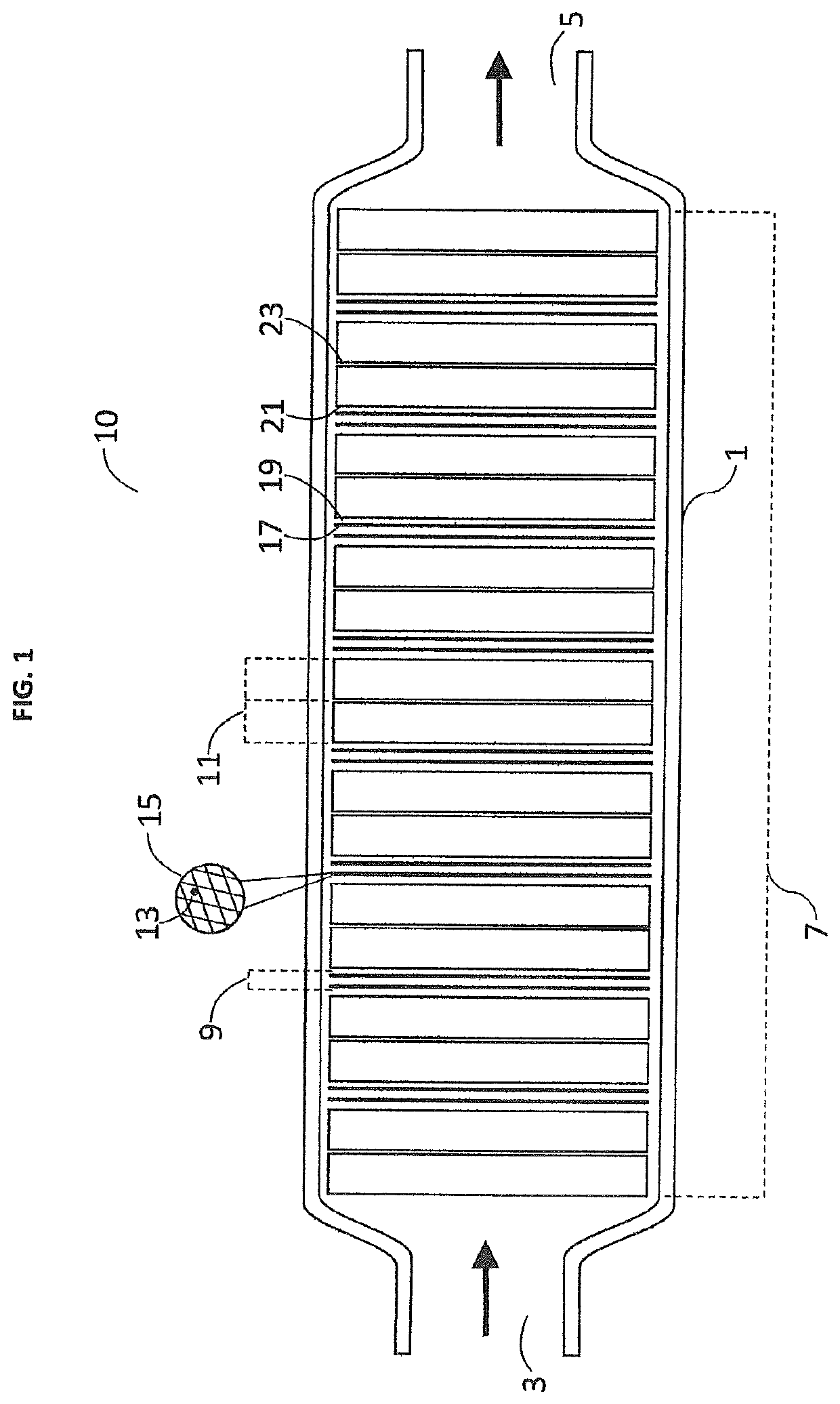
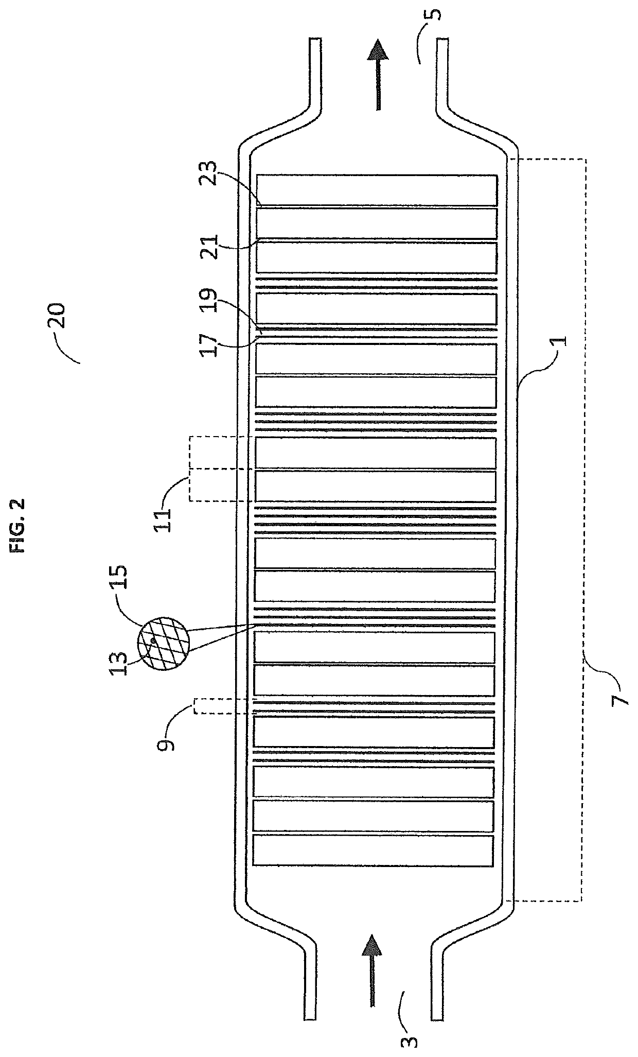
[0095]A catalytic reactor of this invention was constructed in accordance with FIG. 1, comprising a plug flow reactor with specific internal structures featured in this invention. The plug flow reactor consisted of a stainless steel housing of tubular shape (1.1 inch, 27.5 mm I.D.), having disposed therein 26 porous catalytic elements in the form of screens having a length in the direction of flow of 0.007 inch (175 μm) (MICROLITH brand mesh, Precision Combustion, Inc., North Haven, Conn.). The tube was open at both ends providing for an inlet and an outlet and an axial flow path along the length of the tube from inlet to outlet. Each catalytic screen consisted of expanded iron-chromium alloy coated with an alumina washcoat (20 mg / in2 areal loading) covered with a dispersion of metallic rhodium (2 mg / in2 areal loading). Each screen was cut into a circle (27.5 mm dia.) and disposed along the inner volume of the tube. Interspersed between each pair of 2 catalytic screen...

example 2 (

E-2)

[0099]Example E-1 was repeated, with the exception that the flow rates were adjusted to the following: 0.5 slpm methane, 0.5 slpm carbon dioxide, and 0.25 slpm nitrogen. Results are presented in FIGS. 6 and 8.

example 3 (

E-3)

[0102]Example E-1 was repeated with the exception that flow rates were adjusted to the following: 2.0 slpm methane, 2.0 slpm carbon dioxide, and 1.0 slpm nitrogen. Results are presented in FIGS. 9 and 11.


PUM

PropertyMeasurementUnit
Lengthaaaaaaaaaa
Lengthaaaaaaaaaa
Fractionaaaaaaaaaa

Abstract

A catalytic reactor constructed of a thermally conductive housing defining a reaction zone having disposed therein: (a) a plurality of catalytic elements, each comprising a porous material having a catalyst supported thereon, and (b) a plurality of heat transfer elements, each comprising a porous, thermally conductive, and essentially catalytically inactive material; wherein the plurality of catalytic elements and the plurality of heat transfer elements are disposed in an alternating configuration within the reaction zone. The catalytic reactor is useful in chemical reactions where heat transfer is a rate limiting step.

Description

CROSS-REFERENCE TO RELATED APPLICATIONS[0001]This application claims benefit of U.S. provisional patent application No. 62 / 945,297, filed Dec. 9, 2019.GOVERNMENT RIGHTS[0002]This invention was made with support from the U.S. Government under Contract No. DE-SC0015855, sponsored by the Department of Energy. The U.S. Government has certain rights in this invention.FIELD OF THE INVENTION[0003]This invention pertains to a catalytic reactor apparatus for use in endothermic and exothermic chemical reactions. This invention also pertains to a first process of operating an endothermic chemical reaction and further pertains to a second process of operating an exothermic chemical reaction.BACKGROUND OF THE INVENTION[0004]To sustain an endothermic chemical reaction, heat must be supplied into a reaction zone of a chemical reactor. The reaction zone typically houses a catalyst facilitating the chemical reaction. In such endothermic reactions, undesirable chemical byproducts may be produced, or ...

Claims


Application Information

Patent Timeline
IPC IPC(8): C01B32/40B01J35/04B01J35/02B01D53/86
CPCB01D53/864B01J35/023B01J35/04C01B32/40B01D2255/904B01D2255/9202B01D2255/9205B01D2257/502B01J37/0225B01J23/464B01J21/04B01J23/8906B01J8/0221B01J8/0285B01J8/0438B01J8/0496B01J2208/00115B01J19/2495B01J2208/025B01J2208/00513B01J35/40B01J35/56
Inventor SMITH, WARREN FWEISSMAN, JEFFREY GSINGH, PRAYUSH
Owner PRECISION COMBUSTION
Learn More