
Method and system for renewing spent fluid catalytic cracking (SFCC) catalysts using acid leaching and acid reflux activities

Active Publication Date: 2022-05-03
VIETNAM PETROLEUM INST
View PDF3 Cites 0 Cited by
  • Summary
  • Abstract
  • Description
  • Claims
  • Application Information

AI Technical Summary

Benefits of technology

The present invention provides a novel method and a large-scaled SFCC recovery system to recycle SFCC, recover rare earth elements, and achieve safety and cost-effectiveness. The invention also improves the efficiency of acid leaching by controlling the acid concentration, ratio of SFCC catalyst to oxalic acid, and temperature of the process. Additionally, the invention provides a simple and low-cost method to convert SFCC catalysts into flushing cats, which results in partial removal of metal impurities, maintains catalyst particle size, and avoids additional granulation processes.

Problems solved by technology

One of the disadvantages of the FCC catalyst is its rapid deactivation which occur both reversibly and irreversibly depending on the conditions of uses or pathways.
E-cats contaminated with a high amount of metal—generally above 4,000 ppm for V and 20,000 for Ni—is not suitable for re-use in FCC.
Despite of their importance, these processes have not been widely developed in industrial scale.
The landfills of SFCC catalysts become costly and prohibitive because of the high concentration of nickel (Ni) in SFCC catalysts.
Eco toxicity, bioaccumulation, and contamination of ground water by these metals are major concerns to human health.
Consequently, the contents of rare earths elements and other valuable metals like vanadium (V) and nickel (Ni) are also lost in the landfills.
Currently, no effective techniques are available in the industrial scale.
Direct reuse as catalyst in other industrial processes has very limited applications, and in lab or pilot-scale only; for instance, SFCC catalysts were used as catalysts for plastic and biomass pyrolysis / gasification or to produce synthetic fuels.
Nonetheless, such processes were not widely used in the industry.
Thus, there have been many attempts to regenerate and recycle SFCC catalysts but none have achieved the desired results, especially in the industrial scale.
However, the method of the '243 patent only concerns with the conversion of a spent FCC (SFCC) into an FCC catalyst containing zeolite without paying attention to (a) the recovery of metals and rare earth elements and (b) to the improvement of the efficiencies of the system.
The '158 patent attempted to recover some of the metals in the SFCC but failed to improve the overall efficiencies of the system.
This is because heating up acids in a closed environment can break the catalyst particles, hampering the objectives of the '158 patent.
In many situations, heating acids in a closed system can be dangerous.

Method used


Image

  • Method and system for renewing spent fluid catalytic cracking (SFCC) catalysts using acid leaching and acid reflux activities
  • Method and system for renewing spent fluid catalytic cracking (SFCC) catalysts using acid leaching and acid reflux activities
  • Method and system for renewing spent fluid catalytic cracking (SFCC) catalysts using acid leaching and acid reflux activities

Examples


examples

[0038]The following examples are intended to be illustrative of the present invention to teach one of ordinary skill in heart to make and use the invention and are not intended to limit the scope of the invention in any way.

examples 1-6 (comparative)

[0039]These examples demonstrate the effects of concentration of acidic solution on the physicochemical properties and catalytic activity of FCC catalyst. The examples also illustrate the criticality of the process parameters.

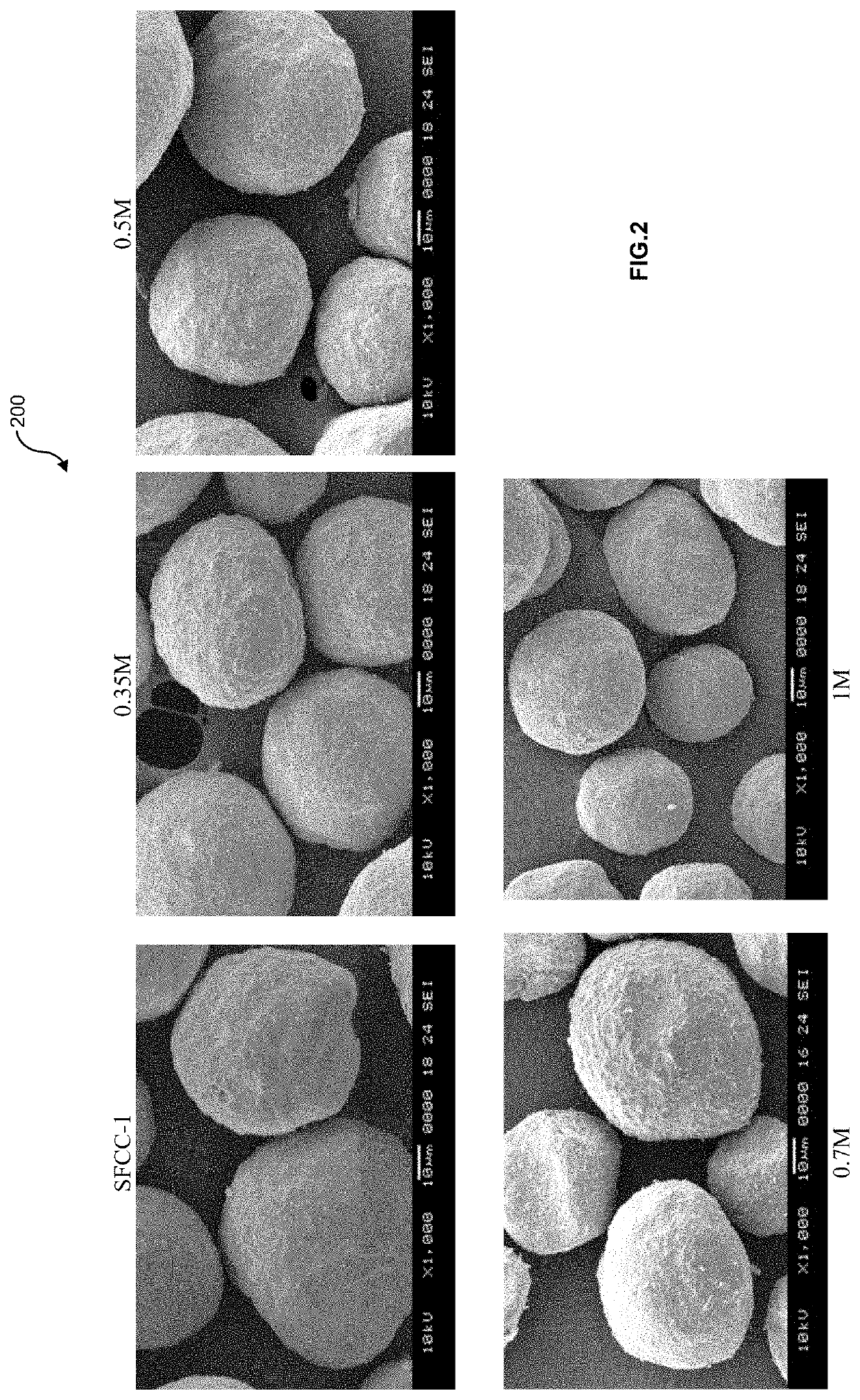
[0040]SFCC-1 catalyst was provided by a Vietnamese refinery in April 2019. In examples 1-6, each 20 g spent catalyst was treated with 100 ml oxalic acidic solution at different concentration 0.2M, 0.35M, 0.5M, 0.7M, 1M and 1.5M within 60 minutes at 100° C., pH 1.5, in reflux.

[0041]The specific surface areas and pore volumes of the catalyst samples were determined by nitrogen adsorption measurement at −196° C. on a Micrometrics TriStar 3020 Micromeritics unit. Samples were prepared using a Micrometrics SmartPrep 065 by degassing under nitrogen flow at 400° C. The zeolite and matrix surface areas were calculated following the ASTM D4365 (2013). The elements content in leachate solution after step i) were determined by ICP method using an ICP-OES spectrometer OPTI...

example 7

[0052]This example determinates the effect of the oxalic acid treatment process in this invention to another SFCC-2 catalyst which were discarded from a Japanese refinery. That SFCC-2 catalyst was treated in the same condition with one in example 3 to compare.

[0053]Example 3 and example 7 have same trend of surface area and cracking activity. After treatment, SFCC-1 and SFCC-2 have all higher surface area in zeolite term as well as matrix term. The same rising trend in cracking conversion was observed in example 7, it increased from 46.4 wt. % to 74.3 wt. %. Bottom cracking was highly improved, HCO yield dropped by approximately 23 wt. % for SFCC-2. The other beneficial products as gasoline and LPG had also a significant increase.

[0054]

TABLE 5Surface area and cracking activity of 2 different SFCC at the sameleaching conditionTreated Treated SamplesSFCC-1SFCC-1SFCC-2SFCC-2Example37Total Surface Area (m2 / g)145186140193Zeolite Surface Area (m2 / g) 8494116138Matrix Surface Area (m2 / g)619...


PUM

PropertyMeasurementUnit
Temperatureaaaaaaaaaa

Abstract

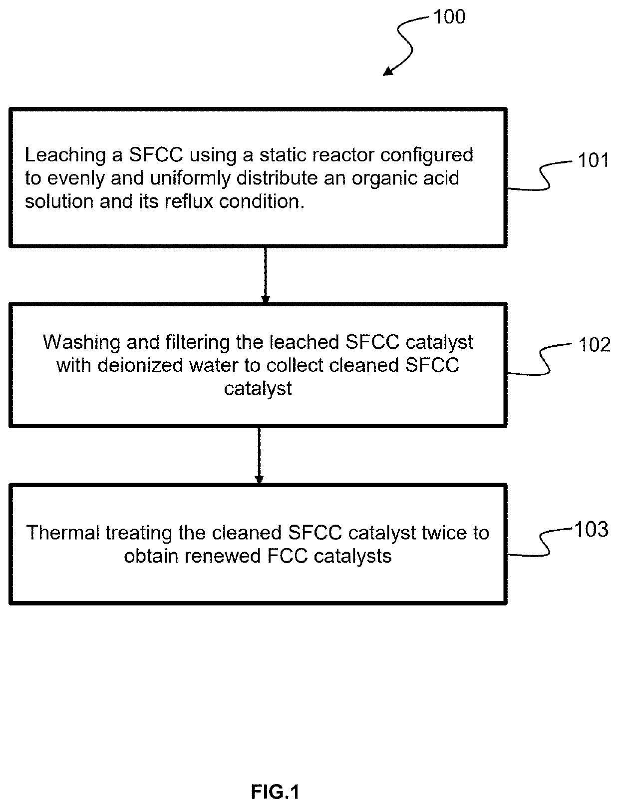
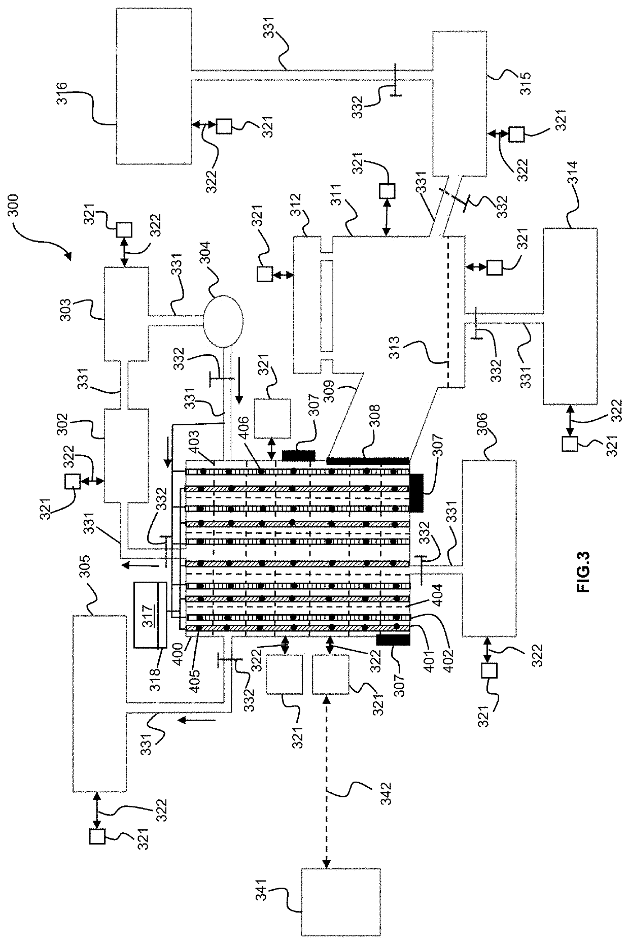
A method and system for renewing spent fluid catalytic cracking (SFCC) catalysts are disclosed which comprises: treating SFCC catalysts using a static reactor designed to uniformly distribute with an oxalic acid solution and its reflux to obtain leached SFCC catalysts; washing with aqueous solution and filtering to collect cleaned and treated SFCC catalyst; and c) executing the cleaned and treated SFCC catalyst with thermal treatment to obtain renewed FCC catalysts.

Description

FIELD OF THE INVENTION[0001]The present invention relates to waste management processes. More particularly, this invention relates to a recovery process for spent fluid catalytic cracking (SFCC) catalysts in petroleum processing plants.BACKGROUND OF THE INVENTION[0002]One of the largest commercial applications in the petroleum refining process is fluid catalytic cracking (FCC). This cracking process uses high temperature and pressure to split vacuum gas oil / atmospheric residues into more valuable lighter hydrocarbons such as gasoline blend components, liquefied petroleum gas (LPG), diesel and other products. The catalysts used up in the FCC process are called equilibrium catalyst (e-cats). Often, the e-cats are either re-used or disposed of as spent FCC (SFCC) catalyst. One of the disadvantages of the FCC catalyst is its rapid deactivation which occur both reversibly and irreversibly depending on the conditions of uses or pathways. Reversible deactivation happens because side reacti...

Claims


Application Information

Patent Timeline
IPC IPC(8): B01J38/62B01J38/02B01J38/72B01J19/00B01D5/00C10G11/18
CPCB01J38/62B01D5/0063B01J19/0033B01J38/02B01J38/72C10G11/182B01J2219/00051B01J2219/00177C10G2300/70B01J29/90B01J35/615
Inventor NGO, PHUONG THUYLE, NGUYEN PHUCTRAN, TRI VANTRAN, THINH HUULUONG, THUY NGOC
Owner VIETNAM PETROLEUM INST
Learn More